Tracked suspension beam assembly

a technology of suspension beams and beams, which is applied in the direction of vehicle maintenance, vehicle cleaning, transportation and packaging, etc., can solve the problems of clogging of tracks, excessive wear, and jamming of suspension components

Active Publication Date: 2007-07-26
BLUE LEAF I P INC
View PDF24 Cites 10 Cited by
  • Summary
  • Abstract
  • Description
  • Claims
  • Application Information

AI Technical Summary

Problems solved by technology

This can clog the tracks, jam suspension components and cause excessive wear, among other problems.

Method used


Image

  • Tracked suspension beam assembly
  • Tracked suspension beam assembly
  • Tracked suspension beam assembly

Examples


Embodiment Construction

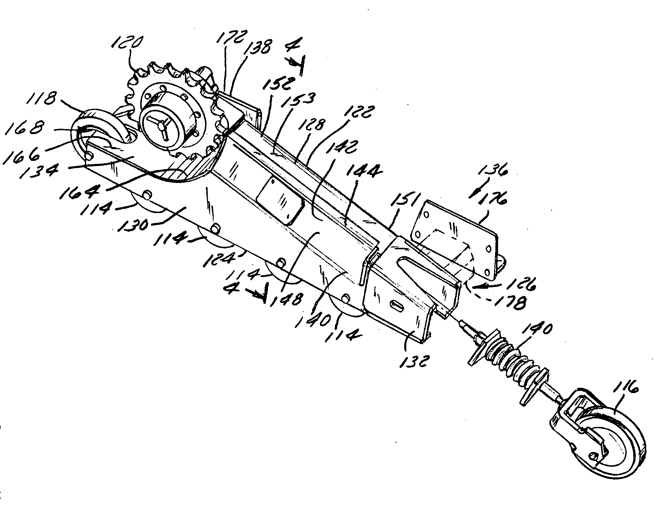
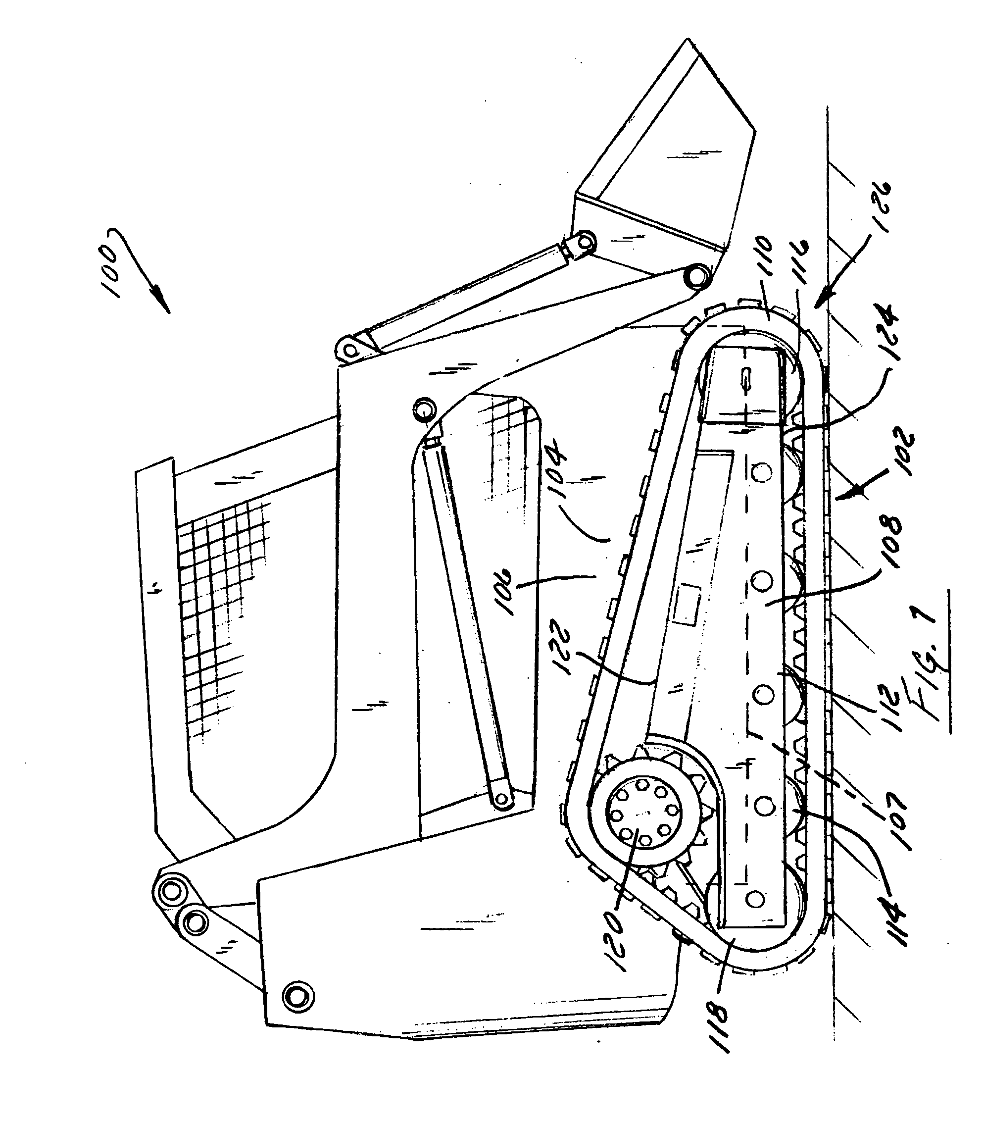
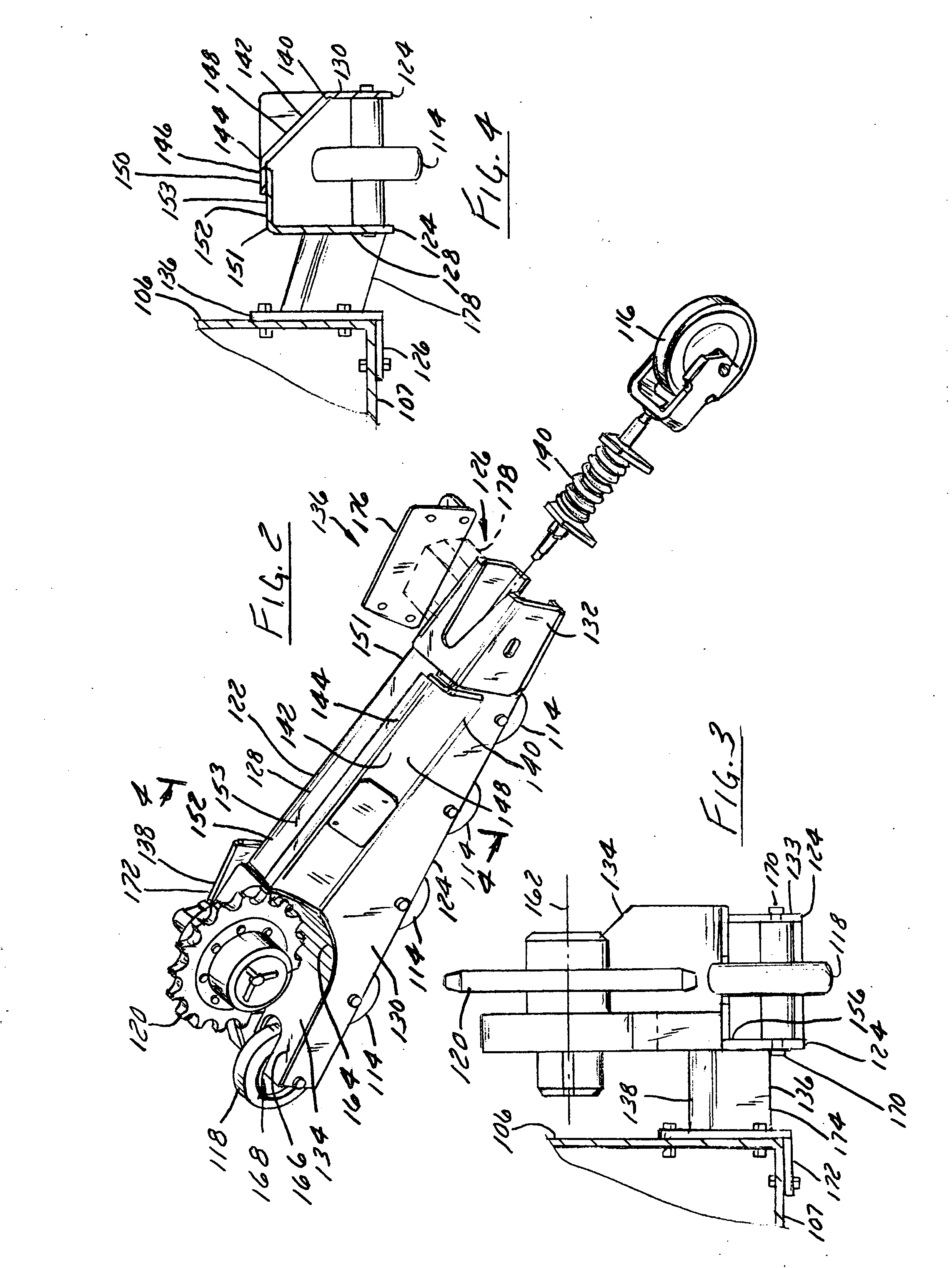
[0012]“Tracked suspension” refers to a suspension for a vehicle configured to travel over the ground by the suspension repeatedly laying and lifting a recirculating track on which the vehicle rests and over which the vehicle travels.

[0013]“Front” or “forward” as used herein, mean the direction and / or location associated with the front end of the vehicle.

[0014]“Rear”, “rearward”, and “backward” refer to a direction and / or location associated with the rear end of the vehicle.

[0015]“Lateral and “laterally” refer to a direction and / or location of a vehicle that is perpendicular to the normal direction of straight forward vehicle travel and is directionally parallel to a ground plane.

[0016]“Lateral angle” as used herein refers to the angle of a surface of a structure as measured in a lateral direction and with respect to the ground. The lateral angle of the surface is an “outwardly descending” angle if the surface so described descends toward the ground as one travels along the surfa...


PUM


Abstract

An elongated beam assembly for a tracked suspension includes an inverted “U” shaped member having a first upper surface disposed at an outwardly descending lateral angle; and a plurality of track wheels coupled to the bottom of the member and disposed inside the member. In another arrangement the assembly includes a curved plate disposed between and fixed to both an inner wall and outer wall of the “U” shaped member, with the free edge of the curved plate extending outward over the top edge of the outer wall.

Description

FIELD OF THE INVENTION [0001] The present invention relates generally to vehicles having tracked suspensions. More particularly it relates to the construction of tracked suspension beams. BACKGROUND OF THE INVENTION [0002] Tracked vehicles are typically designed to operate in fields and construction sites. In these environments dirt and rocks are often churned up and deposited on suspension components. This can clog the tracks, jam suspension components and cause excessive wear, among other problems. What is needed is a suspension that can better shed dirt and other contaminants. It is an object of this invention to provide such a suspension assembly. SUMMARY OF THE INVENTION [0003] In accordance with a first aspect of the invention, an elongated beam assembly for a tracked suspension is provided, comprising an inverted “U” shaped member having a first upper surface disposed at an outwardly descending lateral angle; and a plurality of track wheels coupled to the bottom of the member...

Claims


Application Information

Patent Timeline
Patent Type & Authority Applications(United States)
IPC IPC(8): B62D55/14
CPCB62D55/088B62D55/30B62D55/14B62D55/104
Inventor PLANTE, SEAN M.WAGNER, EDWARD
Owner BLUE LEAF I P INC
Why Eureka
Try Eureka