
Semiconductor LED lamp housing

A technology for LED lamps and LED lamp housings, which is applied to semiconductor devices of light-emitting elements, cooling/heating devices of lighting devices, lighting devices, etc. Insufficient heat dissipation area, etc., to achieve the effect of light weight, beautiful appearance and improved work efficiency

Inactive Publication Date: 2009-01-07
胡凯
View PDF0 Cites 7 Cited by
  • Summary
  • Abstract
  • Description
  • Claims
  • Application Information

AI Technical Summary

Problems solved by technology

The cast aluminum lamp housing radiator used in the prior art can no longer meet the requirements of use. For example, the transmission speed and heat dissipation area of ​​the cast lamp housing radiator are not enough. To meet the heat dissipation, the volume of the radiator needs to be increased, and the volume of the surface radiator is limited. Space restrictions

Method used


Image

  • Semiconductor LED lamp housing
  • Semiconductor LED lamp housing

Examples


Embodiment Construction

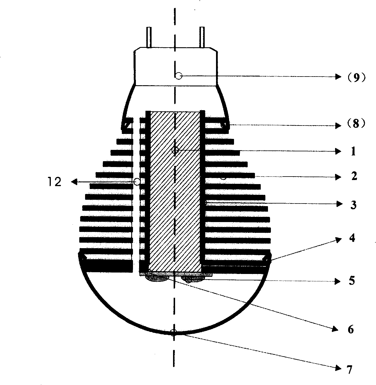
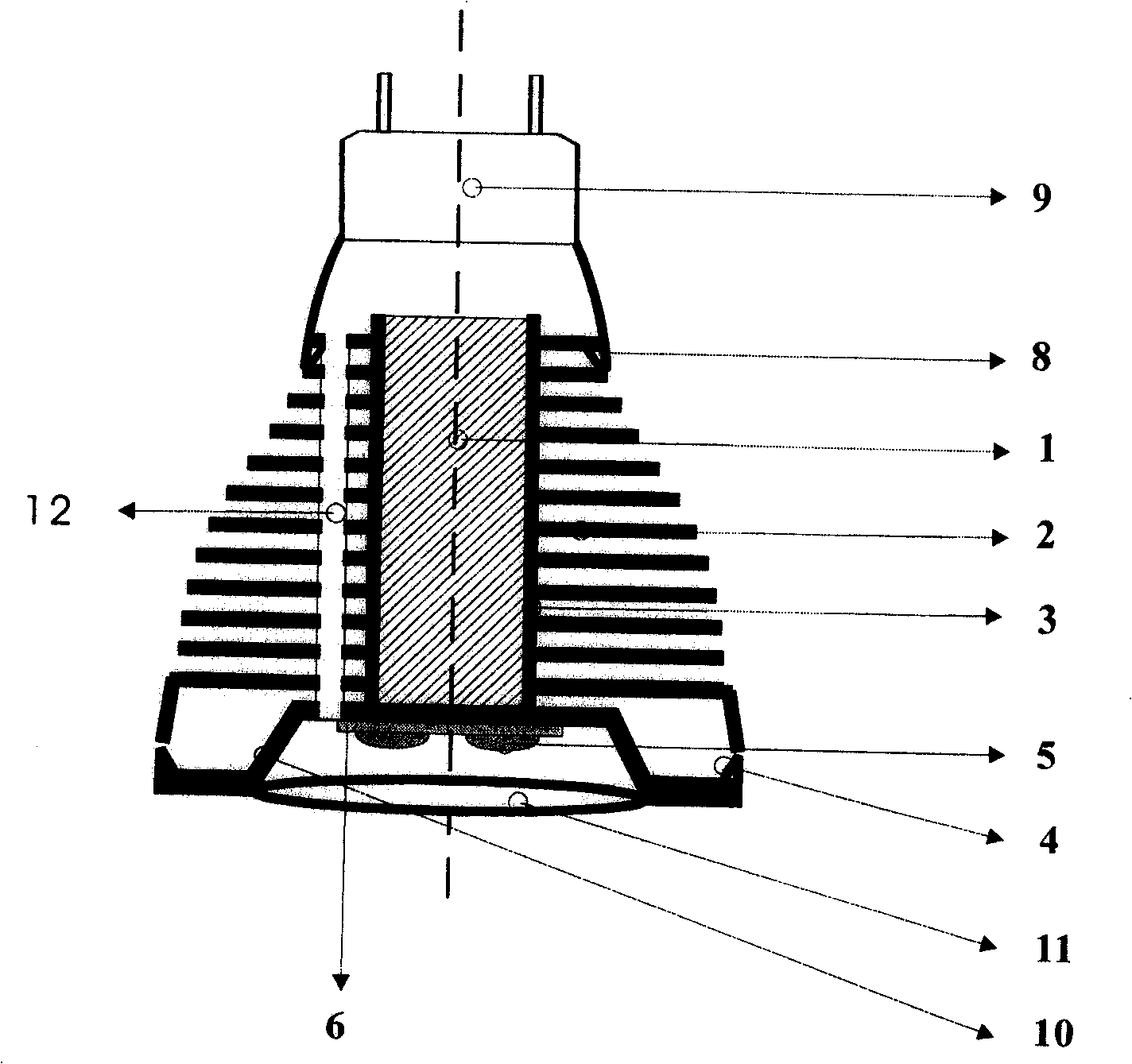
[0009] Referring to the accompanying drawings, the housing of the light-emitting LED lamp includes: a central connecting shaft base (1), thin-plate heat dissipation fins (2) arranged horizontally on the central connecting shaft base (1), and horizontally arranged thin-plate cooling fins (2) overlapped in all parts. The fins (2) are provided with L-shaped flanging fastening holes (3) and wire penetration holes (12), which are used to connect and fix the power supply buckle (8) of the power supply cover (9), and are used to connect and fix the lampshade (7) Or the lampshade buckle (4) of convex mirror lampshade (11).

[0010] plan 1,

[0011] First, process the central connecting shaft base (1) of the lamp housing according to the power of the LED lamp and heat dissipation requirements. The central connecting shaft base (1) can be a heat pipe, a metal blind tube, or a solid cylindrical material. Next, according to the required size of the heat exchange area of ​​the LED lamp, t...


PUM


Abstract

The invention discloses a method for preparing a semiconductor luminescent LED lamp shell with heat radiating function. The invention mainly resolves the technical problems of the existing cast-aluminum lamp shells, such as insufficient heat conductivity, small radiating area, poor quality, etc. Heat pipes or metal dead-hole pipes and solid cylindrical materials are adopted for the central connection-shaft basal-body of the LED lamp shell; the central connection-shaft basal-body is pressed into the fastening holes in the transverse radiating fins by interference adaption and successive penetration; the radiating fin is made of aluminum or copper sheets by punch forming; the diameters of the radiating sheet fins transversely overlapped evenly reduce from bottom to top, and thereby, the outline of an overall LED lamp shell is formed; the lamp shell looks like a cup, an isosceles triangle or other geometric shape seen from a lateral angle. An LED lamp fabricated by the method has the advantages that the heat produced during the operation of the LED element can be absorbed quickly by the central connection-shaft basal-body of the lamp shell, and then heat radiation by exchanging air between the radiating sheet fins and the environment is realized.

Description

Technical field [0001] The invention relates to a manufacturing technology of a light-emitting LED lamp housing, which has heat dissipation function characteristics, an overall lamp housing structure, material and manufacturing process for heat conduction through a central axis base, and transverse thin plate fins arranged on the central axis base for heat dissipation. Background technique [0002] As environmental protection and energy-saving semiconductor light-emitting LED lamps are used more and more widely, the brightness requirements are getting higher and higher, and the volume is getting smaller and smaller, and the heat generated by the LED chips is also increasing. How to quickly dissipate the continuous heat generated by LED lamps, so that LED lamps can work normally within the required temperature, the problem of product heat dissipation has become an important obstacle restricting its performance and development. The cast aluminum lamp housing radiator used in t...

Claims


Application Information

Patent Timeline
Patent Type & Authority Applications(China)
IPC IPC(8): F21V29/00F21V7/20F21Y101/02F21V29/508F21V29/71F21Y115/10
CPCF21Y2101/02F21K9/00F21K9/13F21K9/23F21Y2115/10
Inventor 胡凯
Owner 胡凯
Learn More