Foldable electronic device having a latch mechanism

a technology of electronic devices and latches, which is applied in the direction of instruments, portable computer details, electrical apparatus casings/cabinets/drawers, etc., can solve the problem of difficult manipulation of operating members

Inactive Publication Date: 2007-07-26
HON HAI PRECISION IND CO LTD
View PDF23 Cites 10 Cited by
  • Summary
  • Abstract
  • Description
  • Claims
  • Application Information

AI Technical Summary

Benefits of technology

[0004]What is desired, therefore, is a foldable electronic device having a latch mechanism which more readily allows opening or closing a top member thereof.

Problems solved by technology

However, manipulating the operating member is not easy.

Method used


Image

  • Foldable electronic device having a latch mechanism
  • Foldable electronic device having a latch mechanism
  • Foldable electronic device having a latch mechanism

Examples


Embodiment Construction

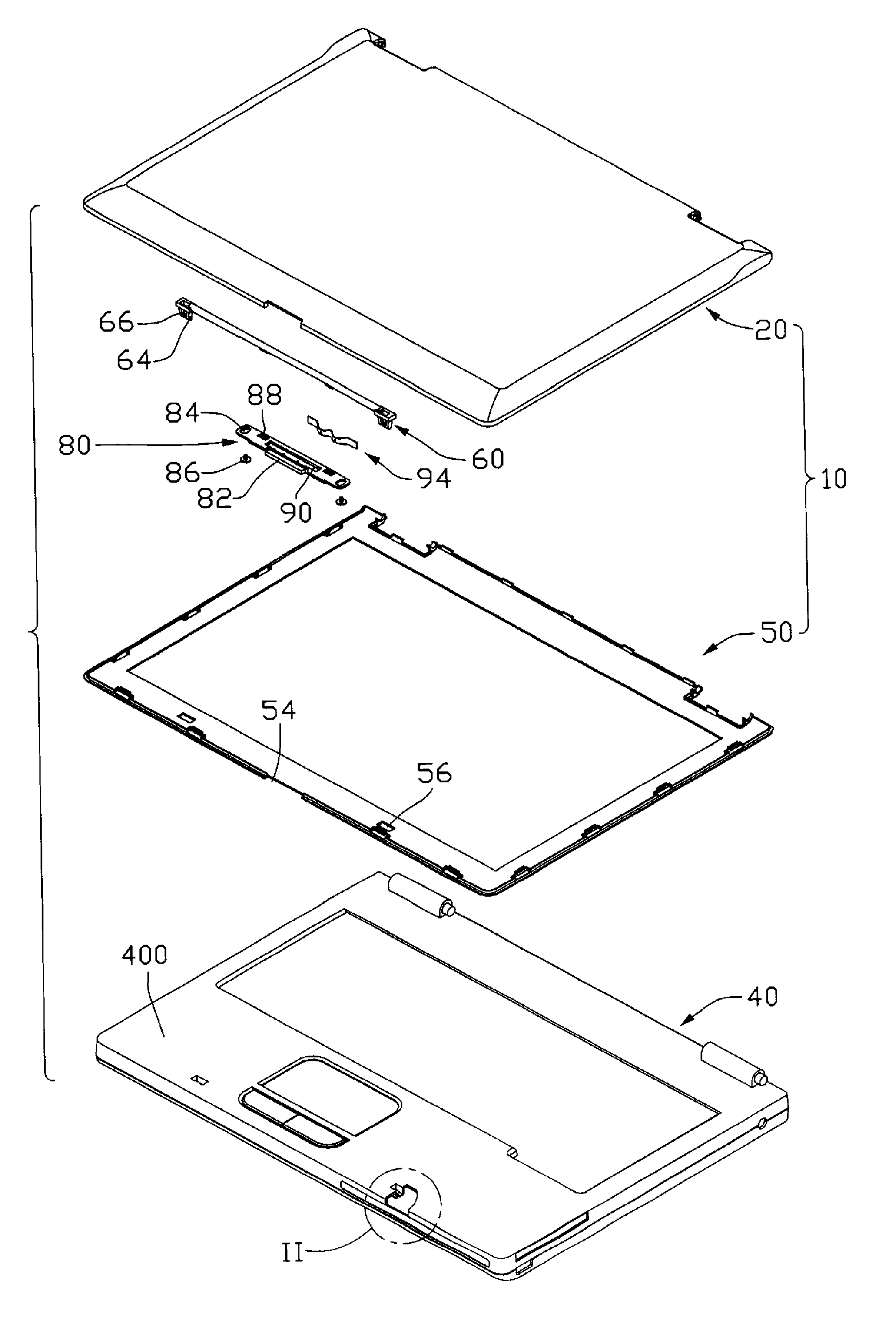
[0013]Referring to FIG. 1, a foldable electronic device in accordance with a preferred embodiment of the present invention is shown. The foldable electronic device of this embodiment is a notebook computer. The notebook computer includes a base member 40, a top member 10 pivotably mounted to the base member 40, and a latch mechanism. The top member 10 includes a cover 20, and a bezel 50. The cover 20 and the bezel 50 are for mounting a liquid crystal display panel (not shown) therebetween.

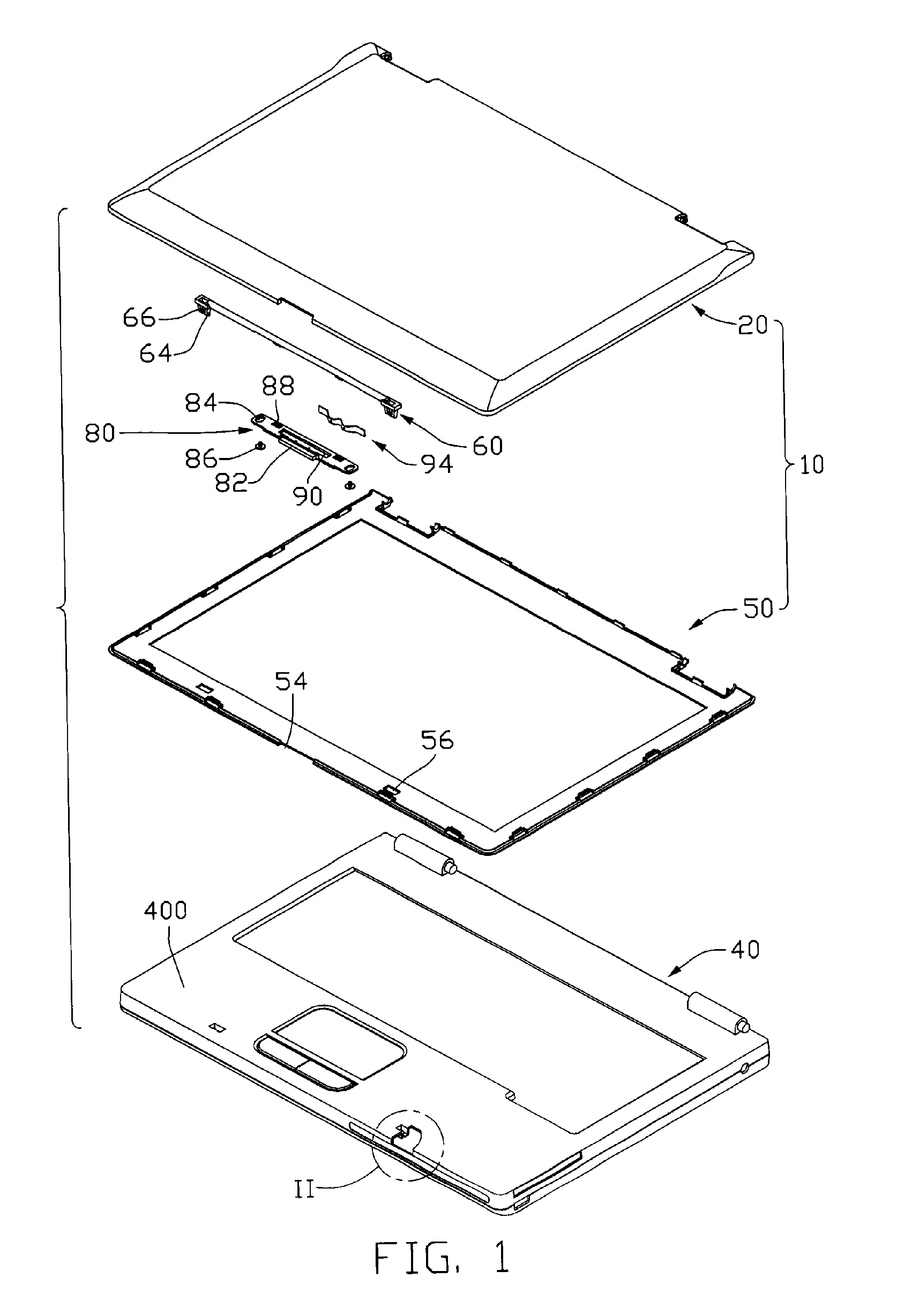
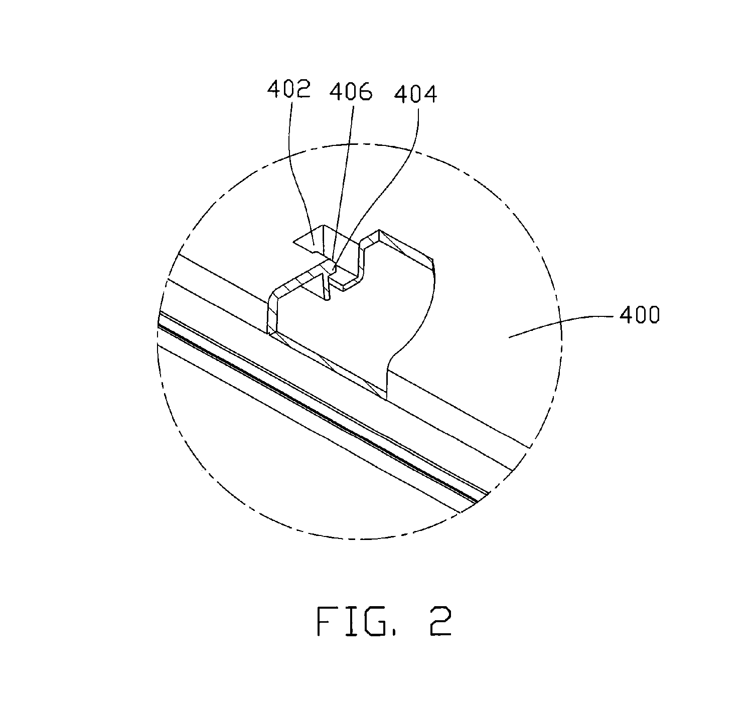
[0014]Referring also to FIG. 2, the base member 40 includes a top wall 400. Two recessed portions 402 are defined in the top wall 400 at a front side of the top wall 400. A protrusion 404 protrudes into each recessed portion 402 from a front side of the recessed portion 402. The protrusion 404 has a slanting guiding surface 406 at a top thereof.

[0015]Referring also to FIG. 3, the cover 20 defines a cutout 24 in a middle portion of a front side thereof. A plurality of mounting tabs 30 extends down f...


PUM


Abstract

A latch mechanism for fixing a top member to a base member of a foldable electronic device includes a locking member, an operating member, and a resilient member. The locking member for being pivotably received by the top member of the foldable electronic device includes a locking portion for engaging with the base member of the foldable electronic device. The operating member for being slidably mounted to the top member includes a driving portion to drive the locking member to pivot. The resilient member is for being mounted between the top member of the electronic device and the operating member.

Description

FIELD OF THE INVENTION[0001]The present invention relates to foldable electronic devices, and particularly to a foldable electronic device having a latch mechanism for readily closing or opening a top member thereof.DESCRIPTION OF RELATED ART[0002]A typical foldable electronic device, such as a notebook computer, includes a base member, and a top member with a rear end pivotably mounted to a rear end of the base member by hinges. Generally, the notebook computer includes a latch mechanism mounted to a front side of the top member for fixing the top member to the base member in a closed position.[0003]A conventional latch mechanism is disclosed in U.S. Pat. No. 6,115,239. The latch mechanism includes a sliding member slidably mounted to a top member of a notebook computer, an operating member mounted to the sliding member, and two springs located between corresponding ends of the sliding member and the top member. The sliding member includes a plurality of L-shaped latches protruding...

Claims


Application Information

Patent Timeline
Patent Type & Authority Applications(United States)
IPC IPC(8): G06F1/16
CPCG06F1/1679G06F1/1616
Inventor HONG, LIN-YUNCHEN, HSUAN-CHENTSAI, CHIEN-LILIANG, CHUN-CHI
Owner HON HAI PRECISION IND CO LTD
Why Eureka
Try Eureka