

Projection-type display apparatus and method for performing projection adjustment
a projection display and projection display technology, applied in the direction of printers, instruments, camera focusing arrangement, etc., can solve the problems of inability to disadvantageously fully serve the intended purpose of the guide display and the difficulty of visually recognizing the displayed contents of the guide display
- Summary
- Abstract
- Description
- Claims
- Application Information
AI Technical Summary
Benefits of technology
Problems solved by technology
Method used
Image

Examples
first example
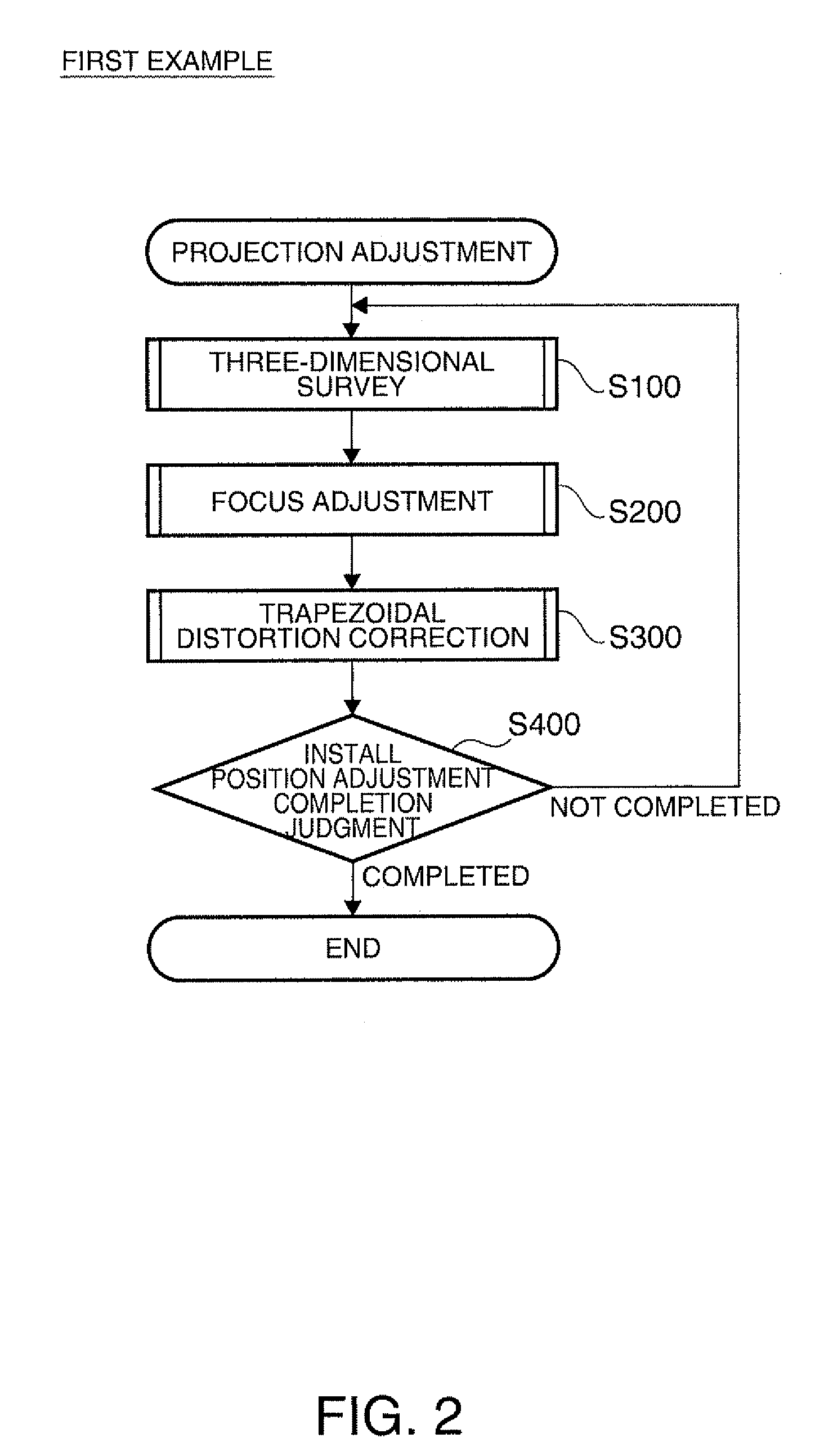
A. FIRST EXAMPLE
A1. Overall Configuration of Projector
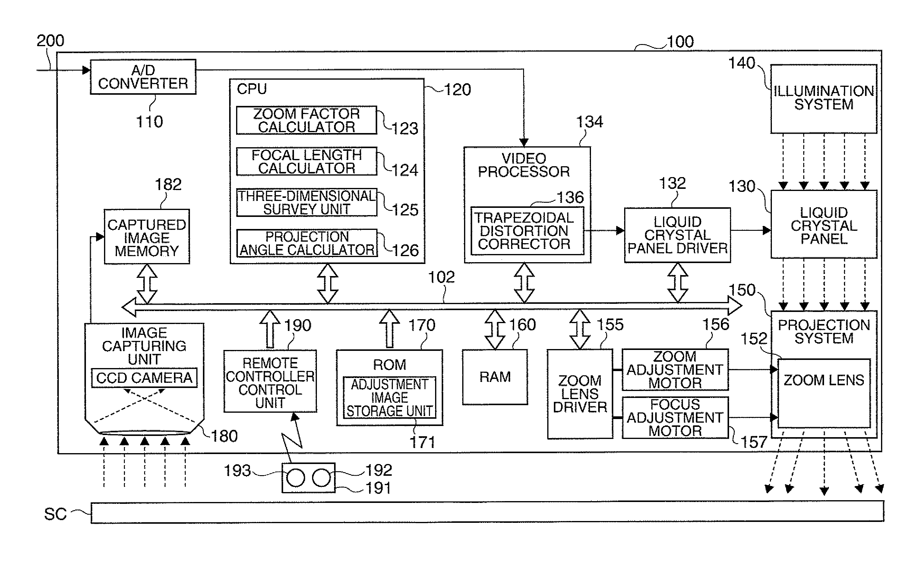
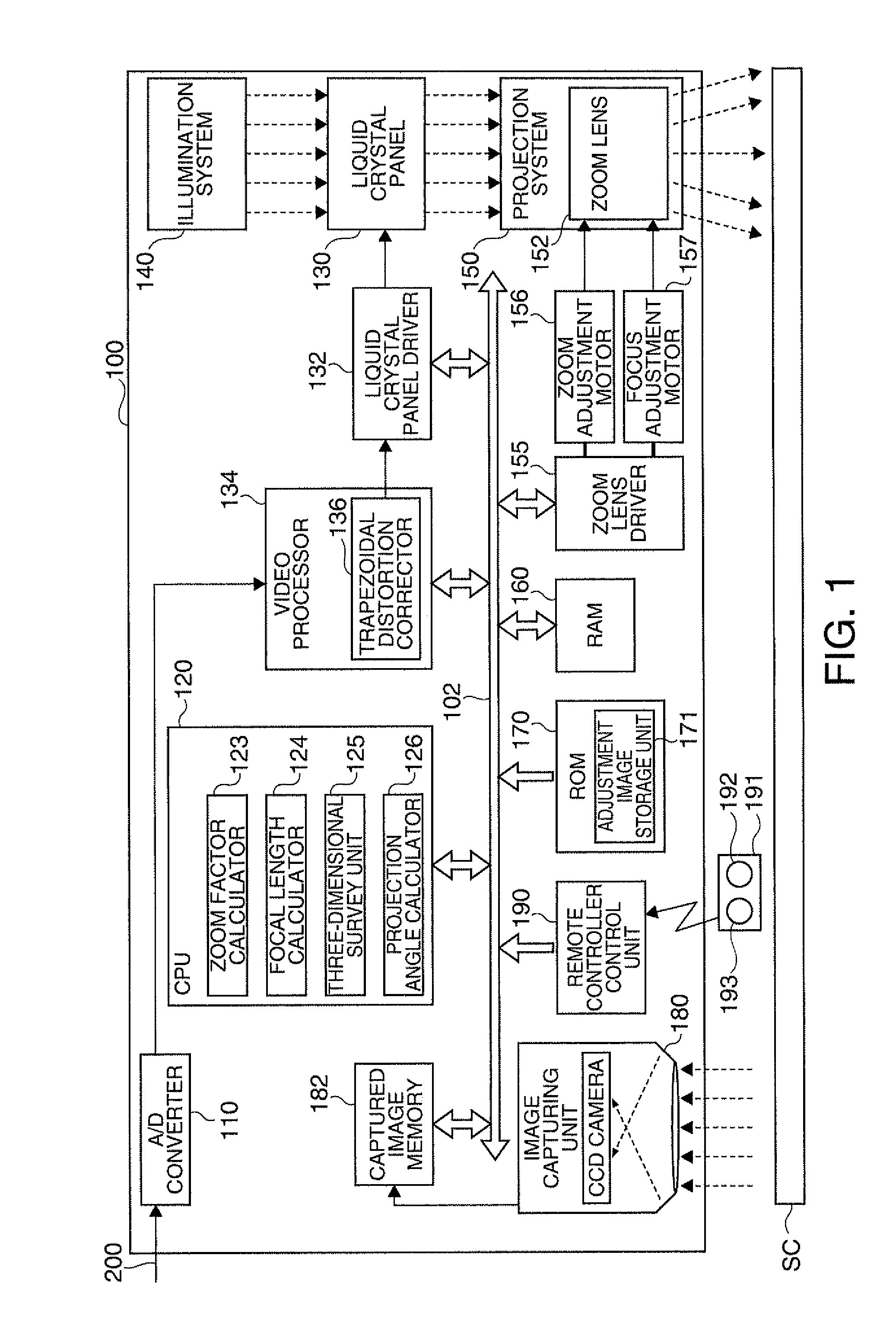
[0055]FIG. 1 is a block diagram showing an overall configuration of a projector 100 in a first example of the invention. The projector 100 externally receives an image signal representing an image and displays the image signal as the image (hereinafter referred to as a “projected image”) on a screen SC or any other suitable projection surface. In the present example, the screen plane has a rectangular shape.
[0056]The projector 100 can be roughly divided into an optical system that forms an optical image and an image processing system that electrically processes a video signal. The optical system includes an illumination system 140, a liquid crystal panel 130, and a projection system 150 and corresponds to the projection section in the claims. The illumination system 140 includes an arc lamp (not shown) and outputs the light from the arc lamp as the light used for projection. The liquid crystal panel 130 receives a signal from the...
second example
B. SECOND EXAMPLE
[0089]A second example will next be described. The second example differs from the first example in that the three-dimensional survey, the focus adjustment, the trapezoidal distortion correction, and the install position judgment are performed in a different order. Since the configuration of the projector and what is done in the three-dimensional survey, the focus adjustment, the trapezoidal distortion correction, and the install position judgment in the present example are the same as those in the first example, no detailed redundant description will be made.
[0090]FIG. 8 shows the procedure of the projection adjustment in the second example. The step labeled with a lower-case alphabetical character appended to the reference numeral indicates that the process in that step is the same as that in the step having the same reference numeral in the first example. First, the user operates the projection adjustment button 192 to initiate the projection adjustment. When the...
third example
C. THIRD EXAMPLE
[0093]A third example will next be described. The third example differs from the first example, as in the second example, only in that the three-dimensional survey, the focus adjustment, the trapezoidal distortion correction, and the install position judgment are performed in a different order. Therefore, no detailed redundant description of the configuration of the projector and the processes performed in the projector will be made.
[0094]FIG. 9 shows the procedure of the projection adjustment in the third example. When the user's operation of the projection adjustment button 192 is detected, the CPU 120 initiates the projection adjustment routine shown in FIG. 9. When the projection adjustment is initiated, the three-dimensional survey (step S100c) is first performed. In the three-dimensional survey, the combined image 330 shown in FIG. 3A is projected on the projection surface, and a plane that approximates the screen is calculated. The CPU 120, which has calculate...
PUM
 Abstract
Description
Claims
Application Information