Valley scuppers for building roofs

a technology for building roofs and valves, which is applied in the direction of roof coverings, roofs, constructions, etc., can solve the problems of low efficiency of water removal, leakage of roofs, and addition of many additional labor costs to the formation of desirable openings, so as to achieve high efficiency, low unit cost, and high efficiency.

Inactive Publication Date: 2006-01-05
BANKS JAMES
View PDF8 Cites 8 Cited by
  • Summary
  • Abstract
  • Description
  • Claims
  • Application Information

AI Technical Summary

Benefits of technology

[0011] It is an additional object of the present invention to provide a valley scupper of the type stated which can be made at a relatively low unit cost and which is highly efficient in operation.
[0012] It is another salient object of the present invention to provide a method of directing water in a valley portion of a roof construction to a downspout or similar member for evacuating the water from the roof construction without the need to specially build up an area to receive a flat bottomed scupper.
[0013] It is still a fu...

Problems solved by technology

Otherwise, water which is pooled on the roof will eventually cause leaks in the roof.
This type of build-up to remove water is not very effective and als...

Method used


Image

  • Valley scuppers for building roofs
  • Valley scuppers for building roofs
  • Valley scuppers for building roofs

Examples


Embodiment Construction

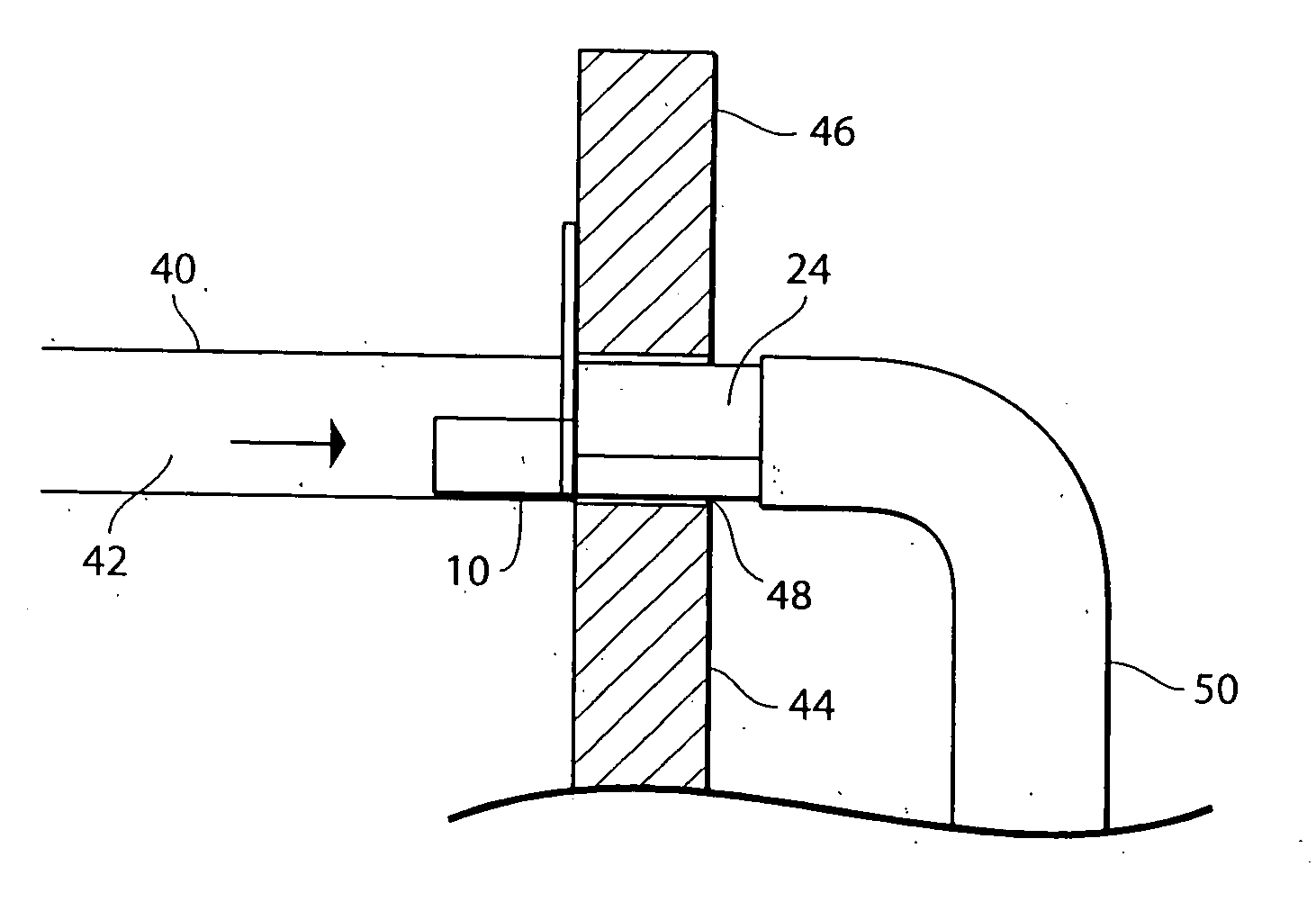
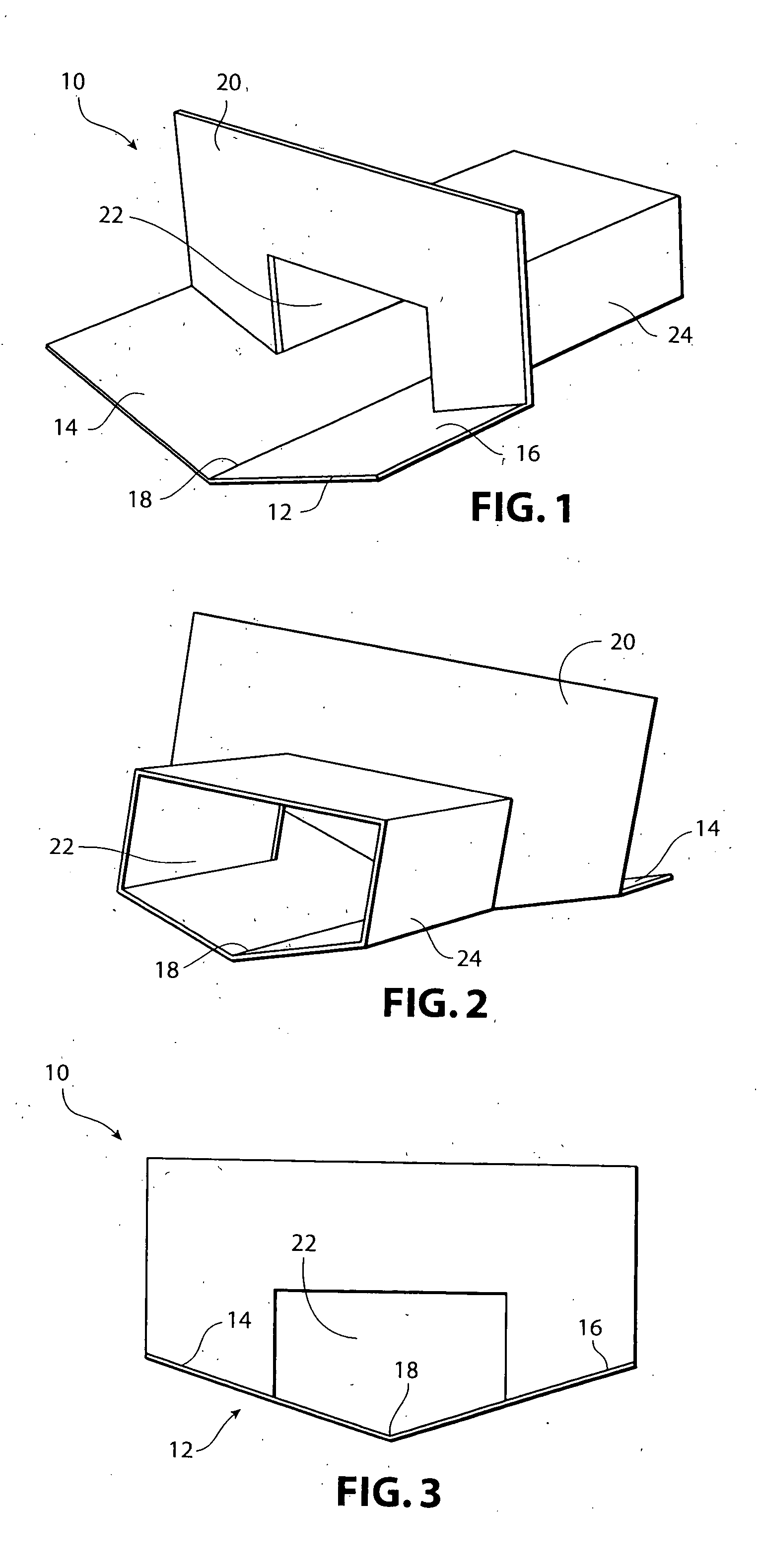
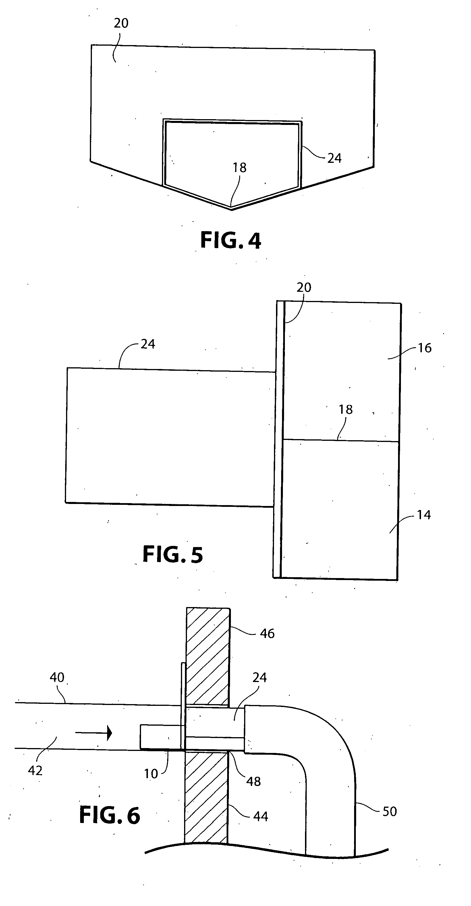
[0030] Referring now in more detail and by reference characters to the drawings, 10 designates a scupper identified herein as a valley scupper used for the draining of water from a roof having angularly arranged roof sections forming a valley therein. The scupper of the invention generally comprises a tray 12 having a pair of flat walls 14 and 16 which are connected at a connecting region 18. The walls 14 and 16 are angulated relative to one another at an angle within the range of 110 to 160 degrees. The most preferred angle is approximately 130 degrees.

[0031] The tray is connected to a vertically arranged upstanding abutment wall 20. The abutment wall 20 has an opening 22 which is generally rectangularly shaped in the manner as best shown in FIGS. 1 and 2 of the drawings. Extending forwardly from the opening 22 and beyond the abutment plate 20 is a tubular drain connecting member 24. By further reference to FIGS. 1-4 of the drawings, it can be seen that the tubular drain connectin...


PUM


Abstract

A valley scupper for use in roof constructions on buildings which have valley portions therein. The scupper comprises an elongate housing which has a somewhat V-shaped lower wall sized to fit within the valley formed in the roof construction. In this way, the scupper is highly effective in collecting water. A reduced size forward end is formed on the scupper, also with a V-shaped construction and is adapted for connection to a downspout.

Description

BACKGROUND OF THE INVENTION [0001] 1. Field of the Invention [0002] This invention relates in general to certain new and useful improvements in apparatus for draining water from the roof of a building and, more particularly, to a scupper which is used on the roof for collecting water in valley portions of the roof and causing delivery of same to a downspout or like water collecting member. [0003] 2. Brief Description of Related Art [0004] In commercially available roof constructions there are frequently used apparatus which allow for water to be delivered from the roof of a building to an exterior portion thereof which allows for that water, such as rain water, to be drained from the building, through a downspout, or other means. This type of device is highly effective where there may be a parapet wall which extends upwardly around the periphery of the roof construction and where it is thereupon necessary to remove rain water from collecting on the roof. The roof is frequently provi...

Claims


Application Information

Patent Timeline
IPC IPC(8): E04D13/00
CPCE04D13/1407E04D13/0431
Inventor BANKS, JAMES
Owner BANKS JAMES
Why Eureka
Try Eureka