

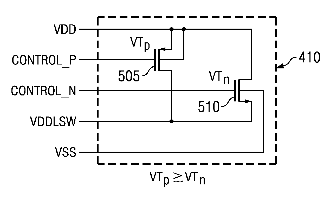
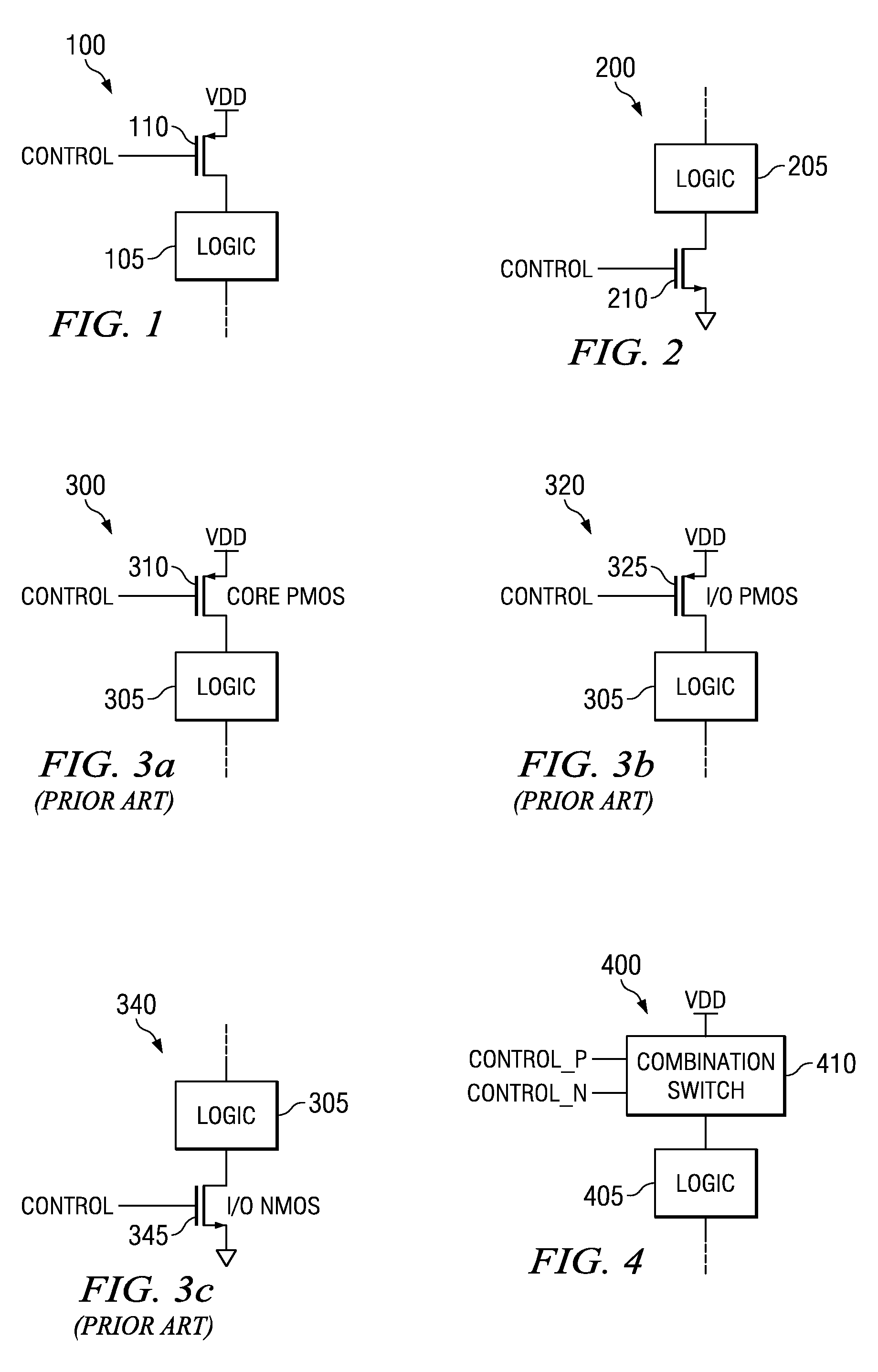
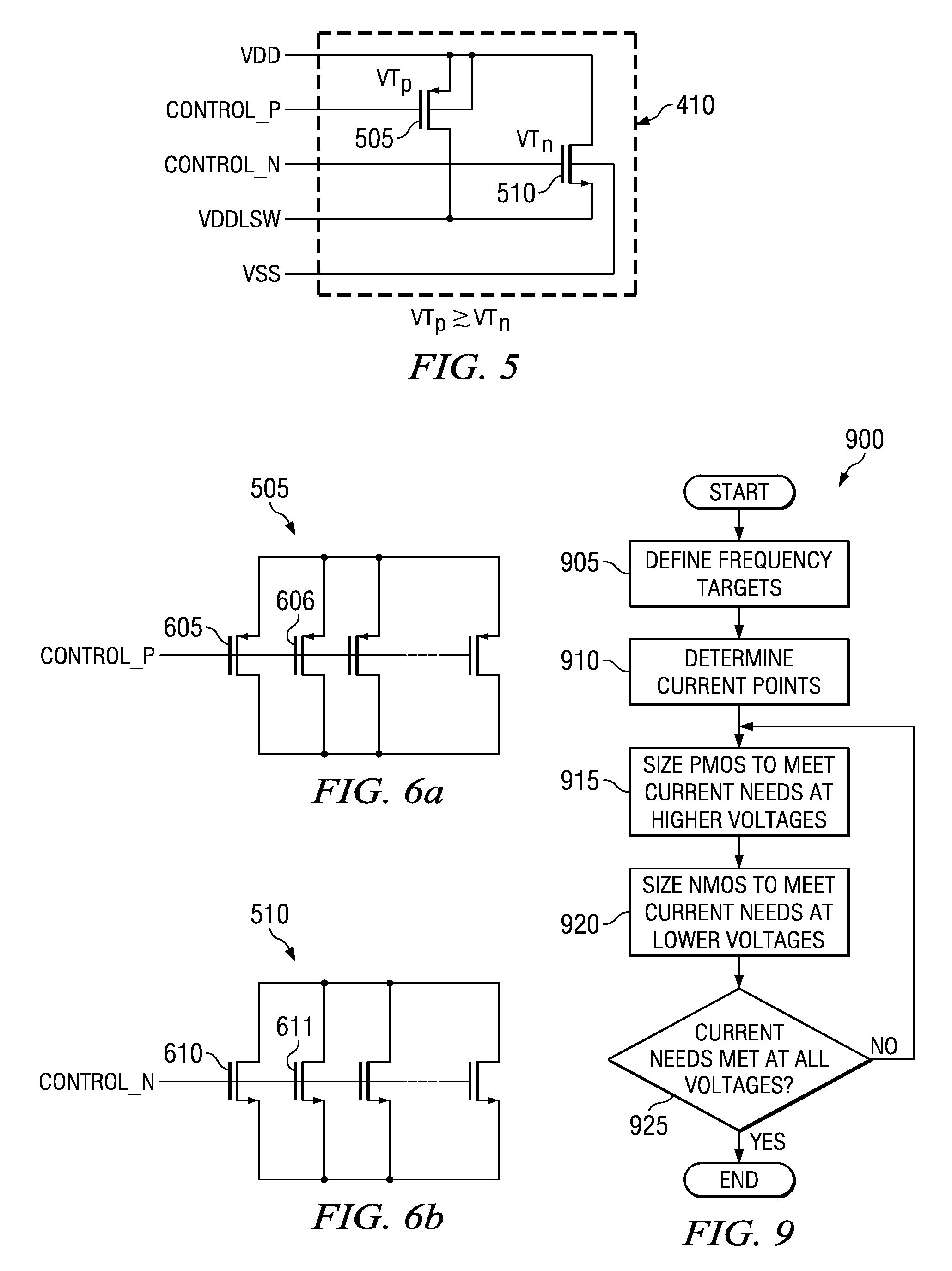
Integrated header switch with low-leakage PMOS and high-leakage NMOS transistors
a header switch and low-leakage technology, applied in logic circuit coupling/interface arrangement, pulse technique, instruments, etc., can solve the problems of large on-current and small off-current, use of high and low threshold voltage transistors may preclude the use of a manufacturing process, and achieve low unit cost for the integrated circuit, easy to adapt, and optimized performance
- Summary
- Abstract
- Description
- Claims
- Application Information
AI Technical Summary
Benefits of technology
Problems solved by technology
Method used
Image

Examples
Embodiment Construction
[0025]The making and using of the presently preferred embodiments are discussed in detail below. It should be appreciated, however, that the present invention provides many applicable inventive concepts that can be embodied in a wide variety of specific contexts. The specific embodiments discussed are merely illustrative of specific ways to make and use the invention, and do not limit the scope of the invention.
[0026]The present invention will be described with respect to preferred embodiments in a specific context, namely a header switch for providing power to logic circuitry in an integrated circuit made using a manufacturing process wherein the process may limit the types of transistors available. The invention may also be applied, however, to header switches for use in integrated circuits manufactured using any of a wide variety of manufacturing processes, from processes with a limited number of transistors types to those with unlimited number of transistor types, where there is...
PUM
 Abstract
Description
Claims
Application Information