Multi-electrode with lateral conductivity control

Active Publication Date: 2007-10-11
AXELGAARD MANUFACTURING COMPANY INC
View PDF23 Cites 39 Cited by
  • Summary
  • Abstract
  • Description
  • Claims
  • Application Information

AI Technical Summary

Benefits of technology

[0013] The connector is disposed over the conductive ink pattern and on the top side of the conductive member, whereas the ink pattern is disposed on the bottom side of the conductive member. This arrangement enables the connectors to be disposed in any selected points within a perimeter of the pattern without affecting current distribution. This flexibility of connector positioning, provided by the present invention, facilitates manufacture of the electrodes. In addition, because the lead wire is not disposed between the conductive pattern and patients' skin, there is no interference with the electr

Problems solved by technology

It is well known that inadequate flexing and shaping of the electrode to a patient's contour can result in an irritation of the patient's skin.
Electrical “hot spots” due to uneven electrode-skin contact can result in a rash or a burning sensation

Method used


Image

  • Multi-electrode with lateral conductivity control
  • Multi-electrode with lateral conductivity control
  • Multi-electrode with lateral conductivity control

Examples


embodiment 54

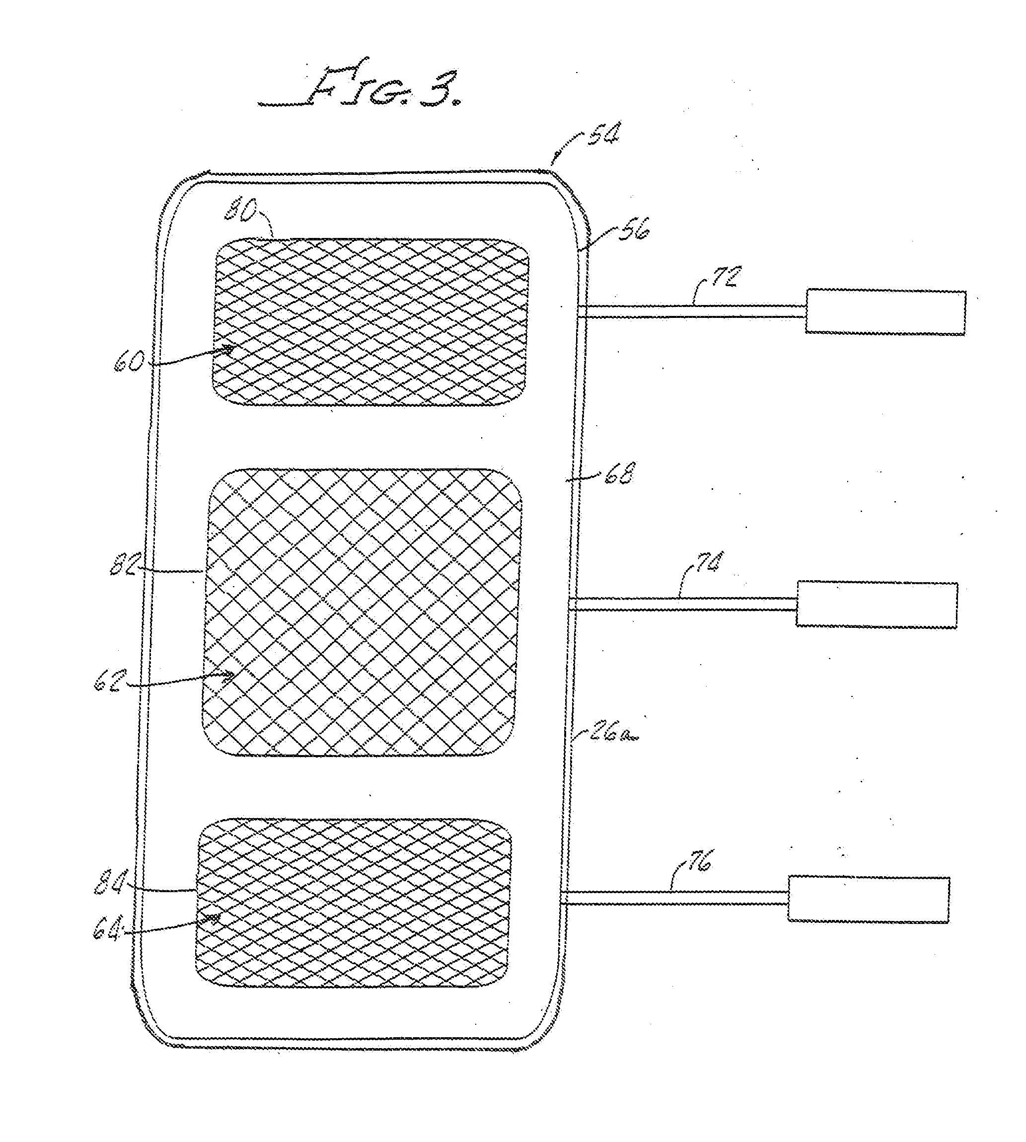
[0043] Shown in FIG. 3 is another electrode embodiment 54 which includes a moderately conductive flexible member 56 having a plurality of highly conductive ink patterns 60, 62, 64 disposed on a bottom side 68 of the conductive member 56. The conductive ink patterns 60, 62 and 64 may be of various shapes and grid patterns in order to customize the electrical conductivity of the electrode 54 beneath the pattern 60, 62, 64. The adhesive, not shown in FIG. 3, is of moderately high conductivity as hereinabove described.

embodiment 10

[0044] The spaced apart patterns 60, 62 and 64 act as separate electrodes and communicate with lead wires, or connectors, 72, 74, 76 respectively, which are attached to a top side (not shown in FIG. 3) of the conductive member 56 as illustrated in FIG. 1 with the description of the electrode embodiment 10.

[0045] The advantage of utilizing a common conductive member 56 with spaced apart ink patterns 60, 62, 64 is that this structure provides uniformity of spacing between the independent electrodes. This in effect provides a template to insure proper electrode placement on a patient's skin.

[0046] It should be appreciated that, as shown in FIG. 3, the connector 72, 74, 76 are in placed over the ink patterns 60, 62, 64. The lead wires 72, 74, 76 may be placed anywhere between the borders 80, 82, 84 of the ink patterns 60, 62, 64 since the current distribution across the electrode gel adhesive 44 is independently controlled as hereinabove noted.

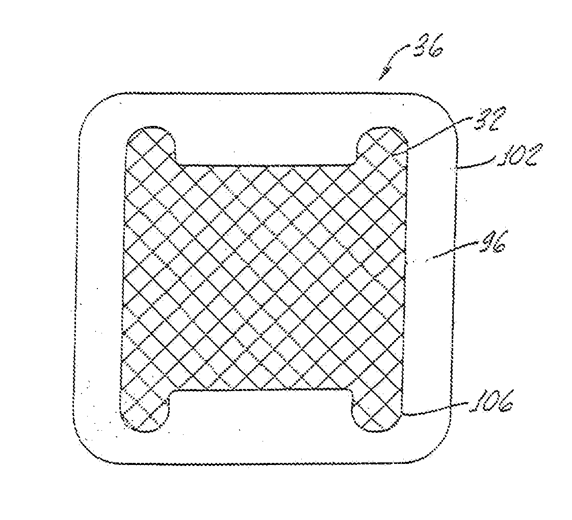
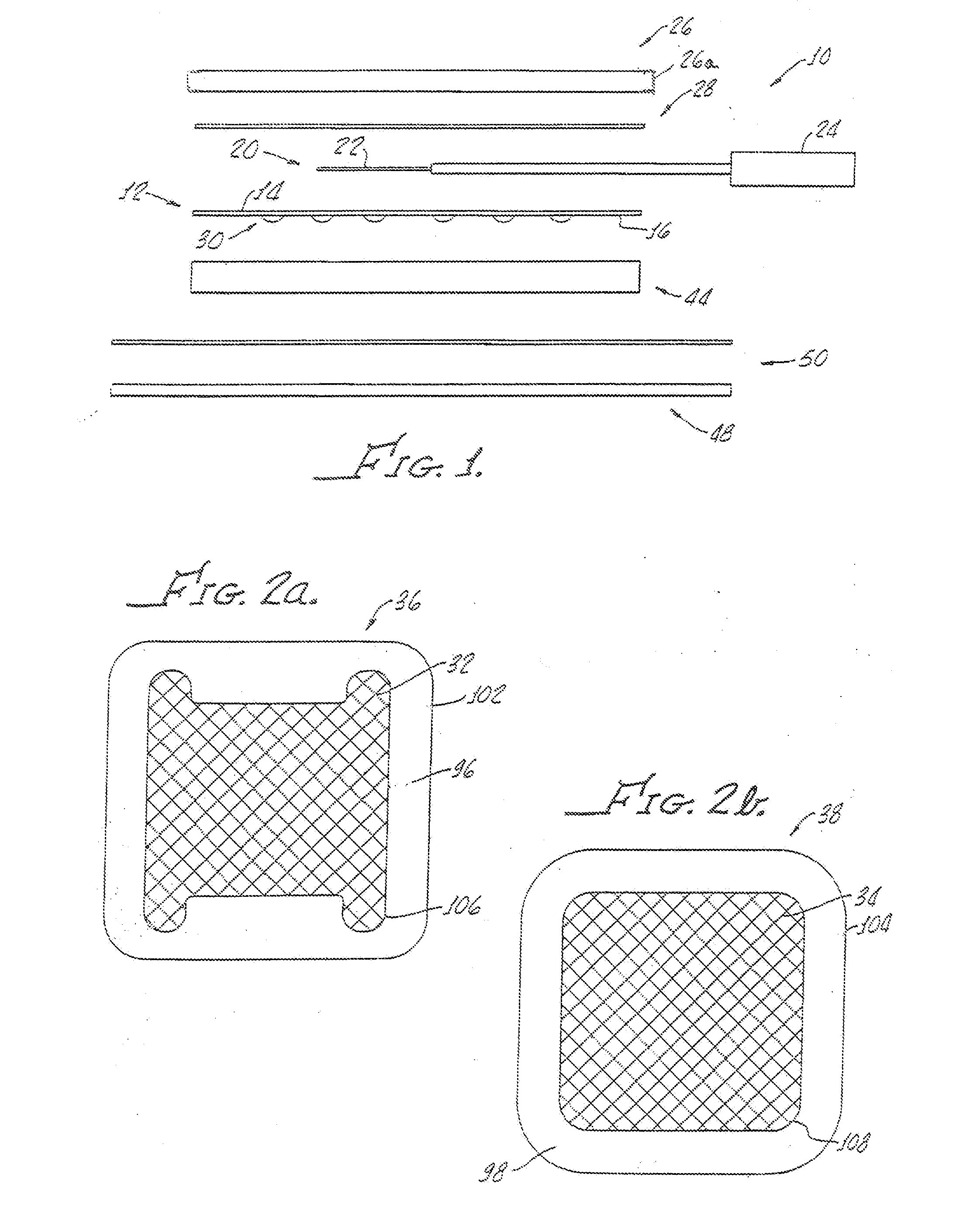
[0047] Referring to FIGS. 2a and 2b, the ...

embodiment 120

[0055] In this embodiment 120, a moderately conductive flexible member 122 includes a top 124 and a bottom 126 with a plurality of highly conductive patterns 130, 132 disposed on the bottom side 126 of the conductive member 122. As hereinabove noted, the conductive patterns 130, 132 may be formed from conductive ink.

[0056] Lateral conductivity between the electrode patterns 130, 132 is controlled by a cutout 140 in a conductive adhesive layer 142 and / or a cutout 144 in the conductive flexible member 122. The cutouts also provide for improved flexibility and conformability of the embodiment 120. Lateral conductivity may also be controlled by varying a thickness of the conductive flexible member and / or conductive adhesive. In that regard, the thickness may not be uniform with variation in thickness used to control lateral conductivity.

[0057] A similar cutout 150 is shown in FIG. 8 in an embodiment 152, similar to the embodiment 54 shown in FIG. 3 with identical or substantially simil...


PUM


Abstract

A medical electrode includes a moderately conductive flexible member having a top side and a bottom side with a connector and contact with a flexible member top side for establishing electrical contact with an external apparatus. An oversize non-conductive flexible sheet covers the conductive flexible member top and the connector and a highly conductive ink pattern is disposed on a conductive flexible member bottom side. A moderately high conductive hydrogel adhesive disposed on the conductive flexible member bottom side and covering the conductive ink pattern is provided for adhering the electrode to a patient's skin. Lateral conductivity and conformability of the electrode is controlled by cutouts in and thickness of the conductive flexible member and/or the conductive adhesive.

Description

[0001] The present application is a continuation-in-part of U.S. Ser. No. 11 / 335,990 filed Jan. 20, 2006 which is a continuation-in-part of U.S. Ser. No. 10 / 359,988 filed Feb. 6, 2003. These referenced patent applications are to be incorporated herein in toto by the specific reference thereto.[0002] The present invention generally relates to electrodes and, more particularly, electrodes suitable for transcutaneous nerve and / or muscle stimulation and biological signal recording. [0003] Medical electrodes must provide an even electrical distribution to a patient's skin over an entire surface of the electrode to assure proper coupling. Because of the curvaceous nature of the human body, it is apparent that medical electrodes for use thereon must be flexible not only for confirmation with a patient's skin contours, but also to accommodate relative movement of the patient's skin. [0004] It is well known that inadequate flexing and shaping of the electrode to a patient's contour can resul...

Claims


Application Information

Patent Timeline
IPC IPC(8): A61N1/04
CPCA61N1/0452A61N1/0456A61N1/0492A61N1/048A61N1/0476
Inventor AXELGAARD, JENS
Owner AXELGAARD MANUFACTURING COMPANY INC
Why Eureka
Try Eureka