X-ray ct apparatus and method of creating correction data for x-ray ct

a correction data and ct technology, applied in the field of xray ct apparatus, can solve the problems of large storage space, large working load, and inapplicability, and achieve the effect of reducing the number of working load

Inactive Publication Date: 2007-07-26
TOSHIBA MEDICAL SYST CORP
View PDF15 Cites 12 Cited by
  • Summary
  • Abstract
  • Description
  • Claims
  • Application Information

AI Technical Summary

Benefits of technology

[0009] Accordingly, it is an object of the present invention to provide an X-ray CT apparatus and a method of creating correction data for X-ray CT, in which correction data can be obtained by using a relatively small-sized phantom, and X-ray absorptance of air and water can be obtained by a one-time scanning sequence.

Problems solved by technology

However, the following problems exist in the methods of acquiring correction data according to the related art.
However, it is difficult to set a phantom whose size is increased in a column direction (bed longitudinal direction) to a bed, which causes a large amount of working loads.
Further, in order to hold a plurality of phantoms whose diameters are different according to the number of detected columns, a large amount of storage space is required, which is not practical.
Accordingly, in order to obtain the X-ray absorptance of the water or the air, it is necessary to perform a scanning operation twice in a state where the phantom is not disposed and a state where the phantom is dispersed, which causes a large amount of working loads.

Method used


Image

  • X-ray ct apparatus and method of creating correction data for x-ray ct
  • X-ray ct apparatus and method of creating correction data for x-ray ct
  • X-ray ct apparatus and method of creating correction data for x-ray ct

Examples


first embodiment

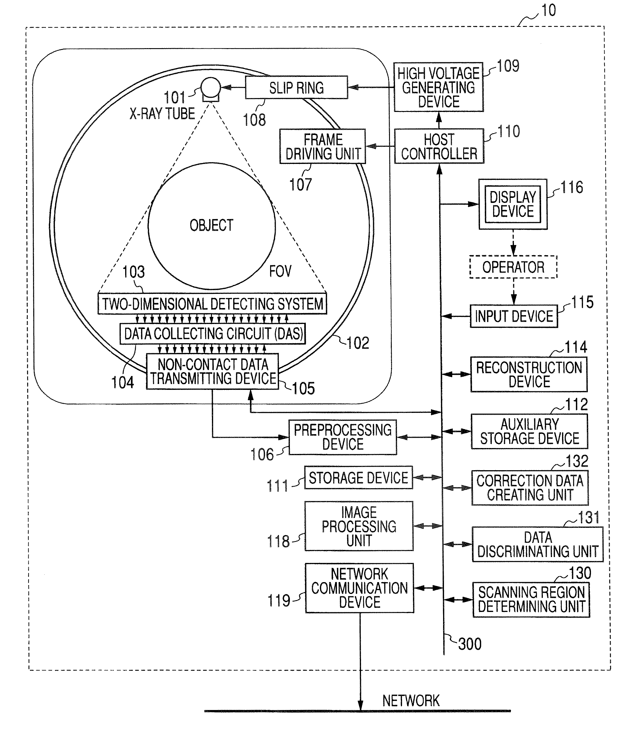
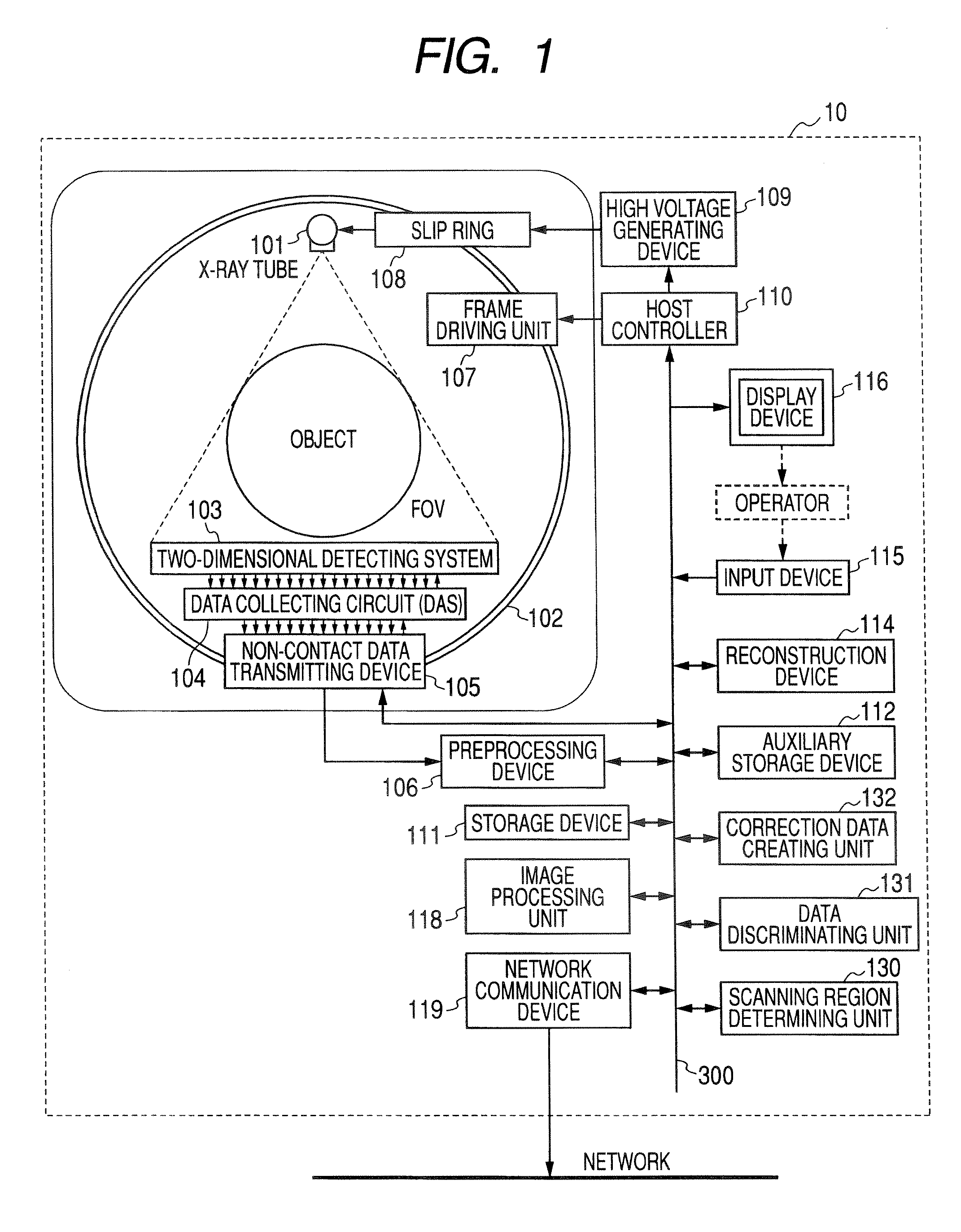
[0025] Hereinafter, an X-ray CT apparatus according to a first embodiment of the invention will be described with reference to the accompanying drawings. Types of the X-ray CT apparatus may include a rotational / rotational type where one X-ray tube and one X-ray detector are provided, and rotate around a subject, and a stationary / rotational type where a plurality of detecting elements are disposed in a ring shape and only an X-ray tube rotates around a subject. The invention may be applied to both the rotational / rotational type and the stationary / rotational type. In this case, the rotational / rotational type that has been mainly used in recent times will be described.

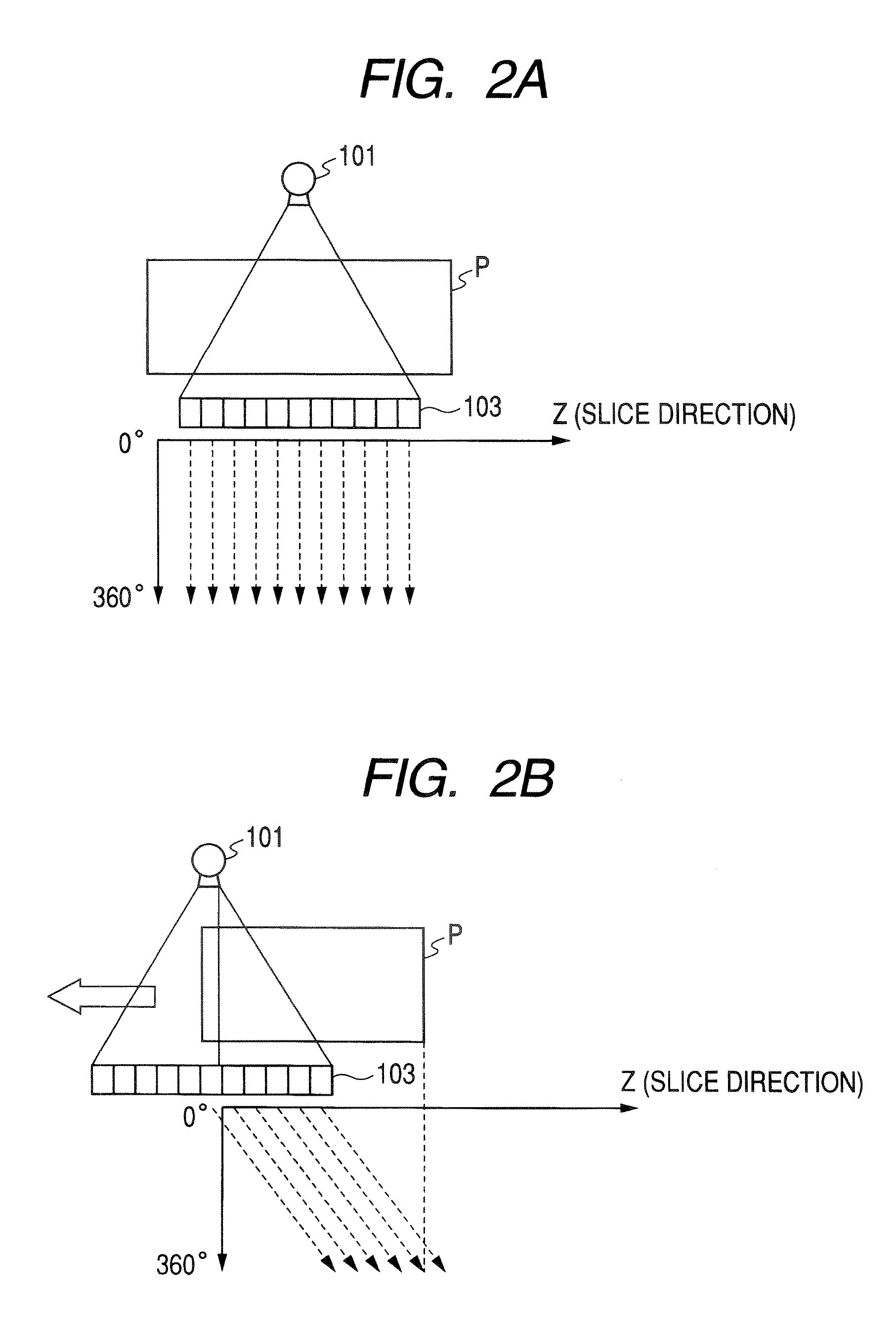
[0026] Further, when reconstructing tomographic image data that corresponds to one slice, projection data that corresponds to one cycle around the subject, that is, approximately 360° is necessary, and even in a half scanning method, projection data that corresponds to 180°+a viewing angle is necessary. Even in all of th...

second embodiment

[0069] Next, a second embodiment of the invention will be described. An X-ray CT apparatus according to the second embodiment uses the difference between the X-ray absorptance of the water and the X-ray absorptance of the air (that is, the difference in the photon counting number) on the basis of the discrimination between the air data and the water data.

[0070]FIG. 5 is a diagram illustrating a discriminating operation between the air data and the water data according to the second embodiment, which illustrates an example of an output profile that is obtained by performing the helical scanning on the scanning region including the water region and the air region and is obtained from an arbitrary detecting element of an arbitrary column from the two-dimensional detecting system 103. In FIG. 5, a horizontal axis indicates a time. However, the positional relationship between the phantom and the two-dimensional detecting system 103 is the same because the moving speed of the bed on whic...


PUM

PropertyMeasurementUnit
angleaaaaaaaaaa
CTaaaaaaaaaa
projection anglesaaaaaaaaaa

Abstract

A helical scanning operation is performed while a bed is moved, so that data by one-time rotation is collected while positional relationships between a detecting system and a phantom relatively are changed. Further, data obtained by scanning an air region and data obtained by scanning a water region are discriminated on the basis of positional information obtained by positioning scanning or the difference between the air and the water in X-ray absorptance, and correction data is created on the basis of the discrimination.

Description

CROSS-REFERENCE TO RELATED APPLICATIONS [0001] This application is based upon and claims the benefit of priority from prior Japanese Patent Application No. 2006-005043, filed Jan. 12, 2006, the entire contents of which are incorporated herein by reference. BACKGROUND OF THE INVENTION [0002] 1. Field of the Invention [0003] The present invention relates to an X-ray CT apparatus having multi-column detectors and a method of creating correction data for X-ray CT, and more particularly, to a technology that is used when creating correction data before photographing a diagnosis image. [0004] 2. Description of the Related Art [0005] Generally, X-ray CT apparatuses calculate (reconstructs) an X-ray absorptance index of tissues, such as internal organs, as indexes like CT values, on the basis of an X-ray absorption amount by which X-rays are absorbed in a subject, and obtain images (tomographic images). These CT values are generally based on the X-ray absorptance of water or air, and are co...

Claims


Application Information

Patent Timeline
Patent Type & Authority Applications(United States)
IPC IPC(8): H05G1/60G01D18/00A61B6/00G01N23/00G21K1/12
CPCA61B6/032A61B6/583G01N2223/419A61B6/027A61B6/4464G01N23/046
Inventor NAMBU, SHUYA
Owner TOSHIBA MEDICAL SYST CORP
Why Eureka
Try Eureka