X-ray CT imaging method and x-ray CT system

a computed tomography and imaging method technology, applied in tomography, instruments, nuclear engineering, etc., can solve the problems of waste, linear linear movement of distance out of an overall distance moved linearly, and not utilized for image reconstruction

Inactive Publication Date: 2005-01-13
GE MEDICAL SYST GLOBAL TECH CO LLC
View PDF10 Cites 20 Cited by
  • Summary
  • Abstract
  • Description
  • Claims
  • Application Information

AI Technical Summary

Benefits of technology

[0007] Therefore, an object of the present invention is to provide an X-ray CT imaging method and an X-ray CT system making it possible to utilize a distance, which is moved linearly for acceleration or deceleration, out of an overall distance moved linearly for the purpose of image reconstruction.

Problems solved by technology

In other words, in conventional X-ray CT systems, a distance moved linearly for acceleration or deceleration out of an overall distance moved linearly is not utilized for image reconstruction but is wasted.

Method used


Image

  • X-ray CT imaging method and x-ray CT system
  • X-ray CT imaging method and x-ray CT system
  • X-ray CT imaging method and x-ray CT system

Examples


first embodiment

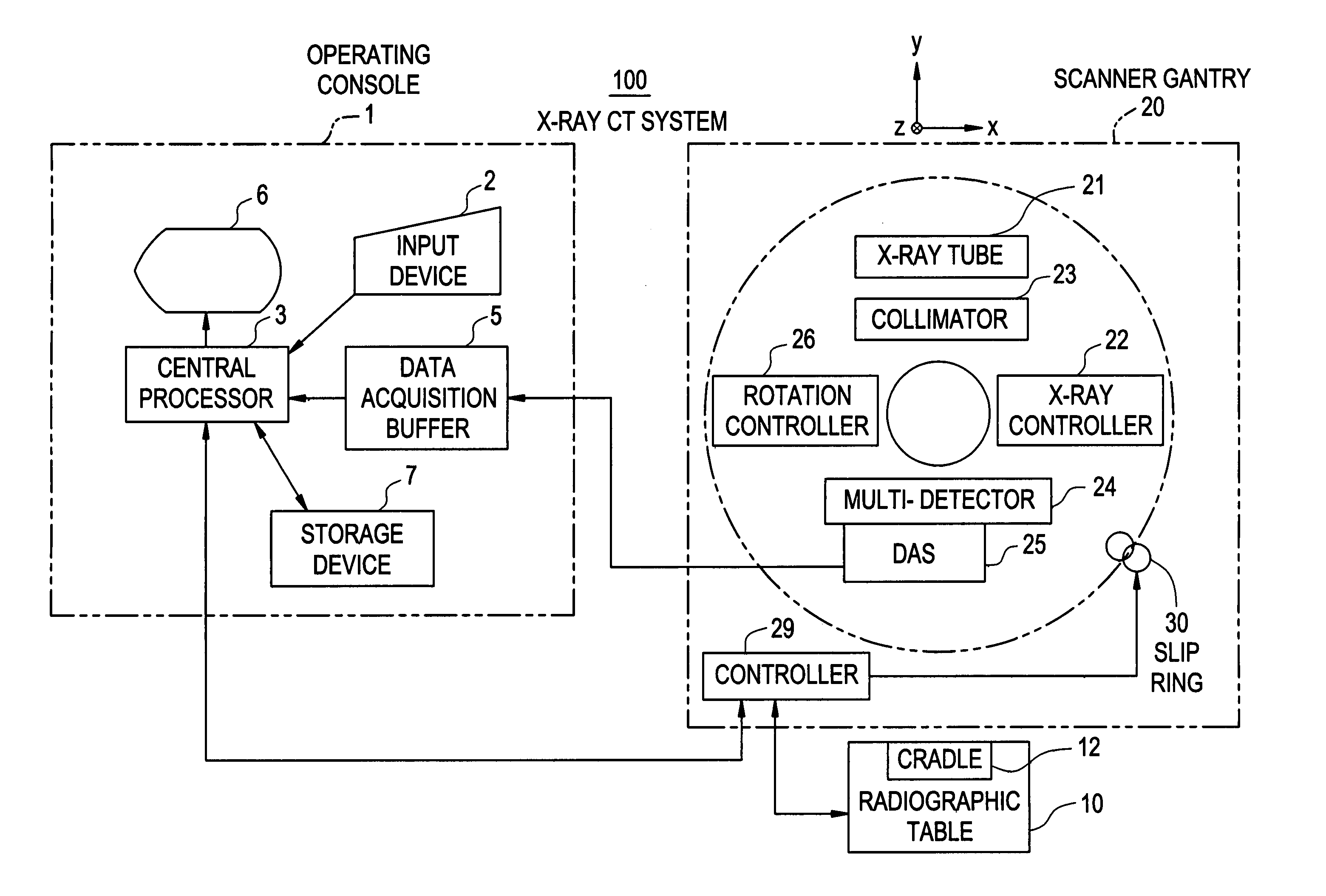
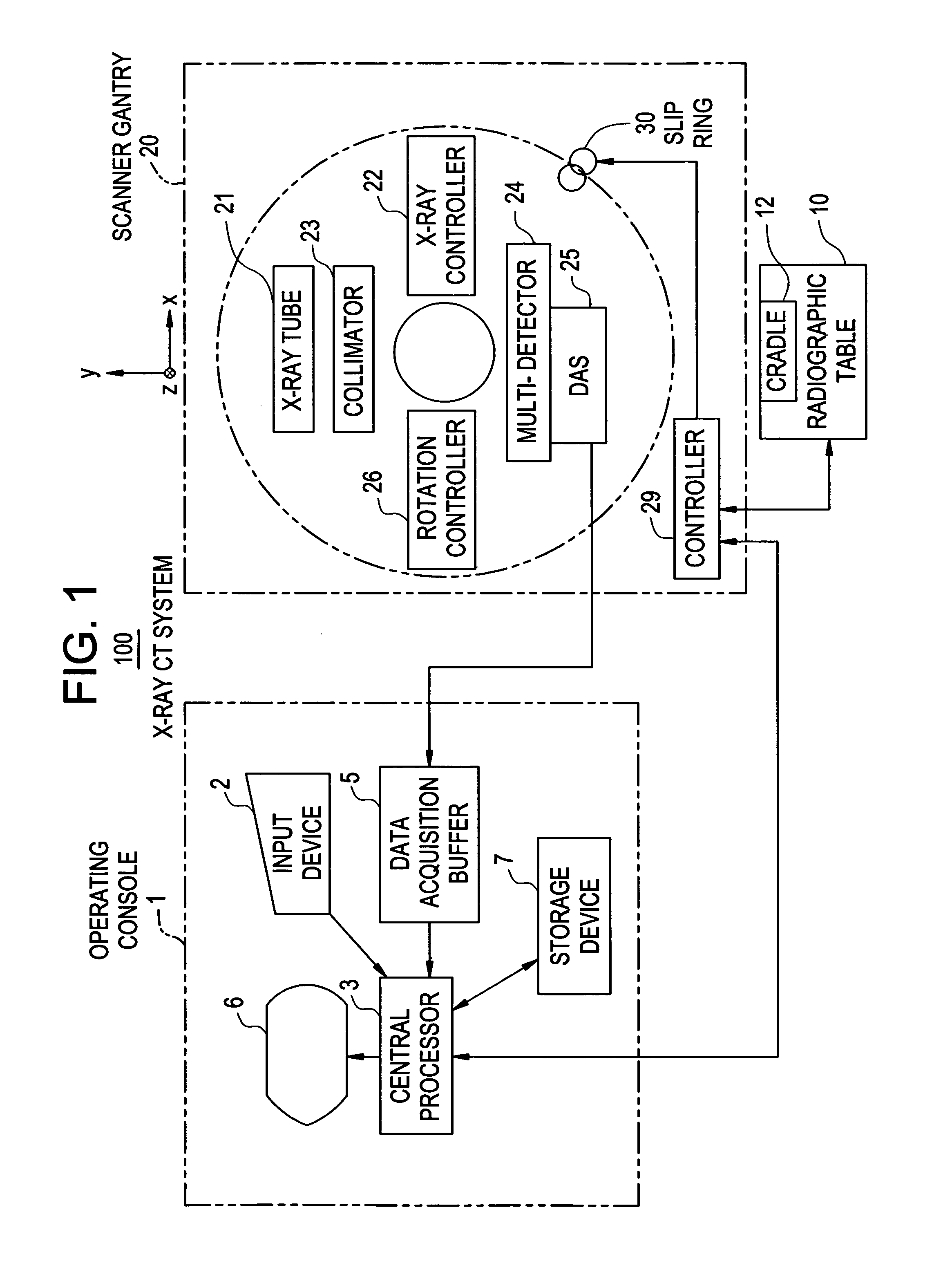
[0096]FIG. 1 is a block diagram showing the configuration of an X-ray CT system in accordance with an embodiment of the present invention.

[0097] The X-ray CT system 100 comprises an operating console 1, a radiographic table 10, and a scanner gantry 20.

[0098] The operating console 1 comprises: an input device 2 that receives an operator's entry; a central processor 3 that executes image reconstruction or the like; a data acquisition buffer 5 in which projection data acquired by the scanner gantry 20 is held; a CRT 6 on which CT images reconstructed from projection data are displayed; and a storage device 7 in which programs, data, and X-ray CT images are stored.

[0099] The table 10 includes a cradle 12 on which a subject lies down and which comes in or out of the bore of the scanner gantry 20. The cradle 12 is lifted, lowered, or linearly moved by a motor incorporated in the table 10.

[0100] The scanner gantry 20 comprises: an X-ray tube 21; an X-ray controller 22; a collimator 23;...

second embodiment

[0149] According to the first embodiment, after views of projection data required for image reconstruction are all acquired at step S1 in FIG. 4, three-dimensional back projection is executed at step S4. In this case, since data acquisition and three-dimensional back projection are performed fully in series with each other, a large time lag is spent until images are produced.

[0150] According to the second embodiment, part of three-dimensional back projection is performed concurrently with data acquisition. Consequently, the time lag spent until images are produced can be shortened.

[0151] In other words, an X-ray CT system in accordance with the second embodiment concurrently executes data processing described in FIG. 29, parameter inference described in FIG. 30, and three-dimensional back projection described in FIG. 31.

[0152]FIG. 29 is a flowchart describing data acquisition executed according to the second embodiment.

[0153] The steps described in FIG. 29 are identical to those...


PUM

PropertyMeasurementUnit
view angleaaaaaaaaaa

Abstract

An object of the present invention is to utilize a distance, which is linearly moved for acceleration or deceleration, out of an overall distance linearly moved during a helical scan for the purpose of image reconstruction. Projection data is acquired even during acceleration or deceleration of linear movement made for a helical scan. The acquired projection data is utilized for image reconstruction. Moreover, during the acceleration of linear movement, while a tube current is being increased, projection data is acquired. During the deceleration of linear movement, while the tube current is being decreased, projection data is acquired.

Description

BACKGROUND OF THE INVENTION [0001] The present invention relates to an X-ray computed tomography (CT) method and an X-ray CT system. More particularly, the present invention relates to an X-ray CT imaging method and an X-ray CT system that can utilize a distance, which is moved linearly for acceleration or deceleration, out of an overall distance moved linearly by a table during a helical scan for the purpose of image reconstruction. [0002] For a helical scan, an X-ray tube and an X-ray detector are rotated about a subject of radiography, and a table on which the subject of radiography lies down is moved linearly. In the linear movement, the table that stands still is accelerated up to a predetermined velocity. When the table enters a zone in which projection data should be acquired, the table is retained at the predetermined velocity. After the acquisition of projection data is completed, the table is decelerated to stand still. The predetermined velocity may be set to different va...

Claims


Application Information

Patent Timeline
Patent Type & Authority Applications(United States)
IPC IPC(8): A61B6/03
CPCA61B6/027A61B6/032A61B6/03
Inventor NISHIDE, AKIHIKOHORIUCHI, TETSUYAHAGIWARA, AKIRA
Owner GE MEDICAL SYST GLOBAL TECH CO LLC
Why Eureka
Try Eureka