
Electron beam computed tomographic scanner system with helical or tilted target, collimator and detector components to eliminate cone beam error and to scan continuously moving objects

a computed tomographic and electron beam technology, applied in tomography, material analysis using wave/particle radiation, instruments, etc., can solve the problems of inability to scan stationary objects in isolation unless, inability to scan single slice of stationary objects in isolation, and inability to obtain data so obtained

Inactive Publication Date: 2006-03-28
GE MEDICAL SYST GLOBAL TECH CO LLC
View PDF4 Cites 21 Cited by
  • Summary
  • Abstract
  • Description
  • Claims
  • Application Information

AI Technical Summary

Benefits of technology

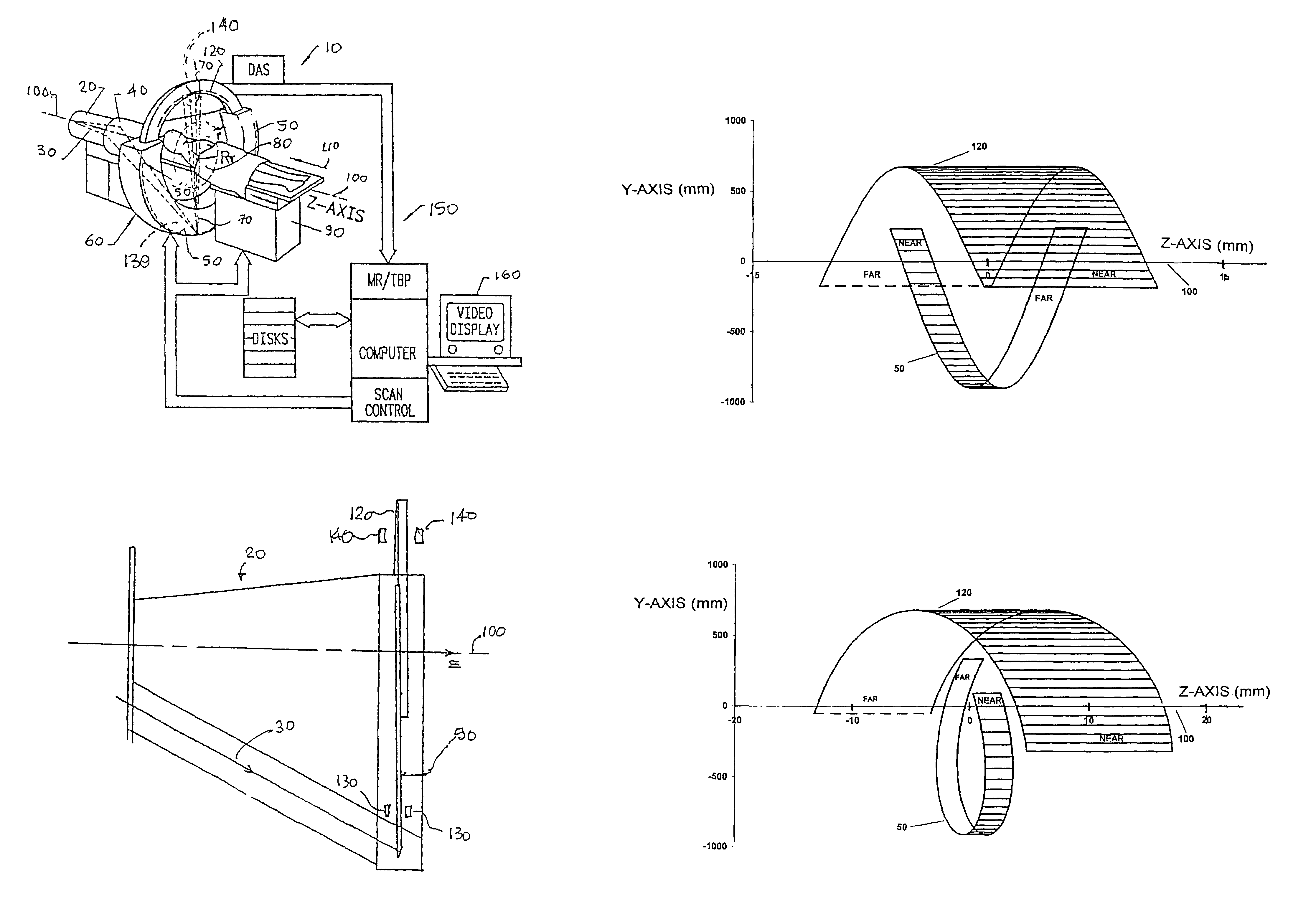
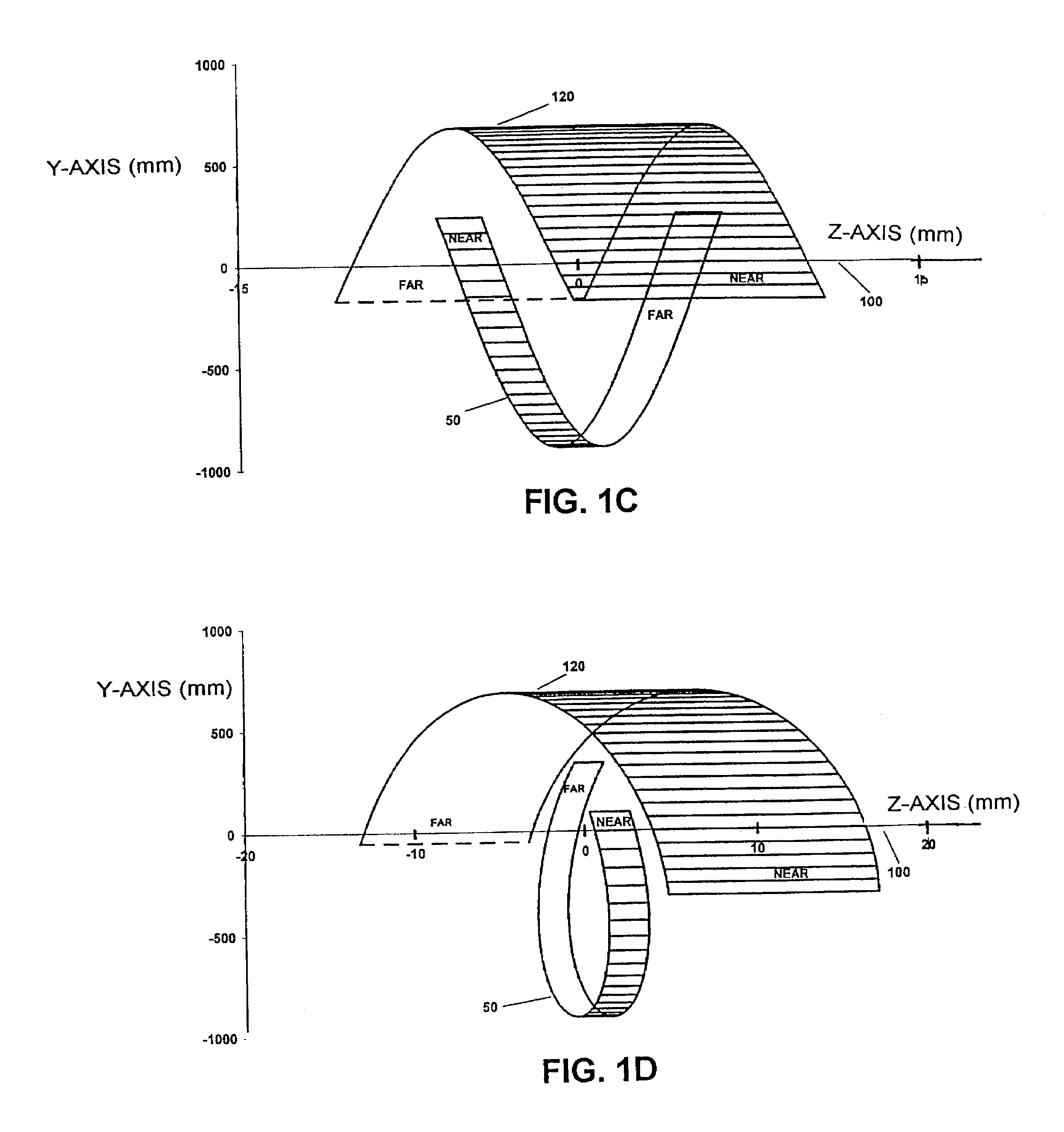
[0014]A scanning electron beam computed tomographic system eliminates axial offset between target and detector, and resultant cone beam error, by disposing the target, detector, and collimator elements such that active regions of the target and detector are always diametrically opposite each other. This result is obtained by using a helical target, helical collimator, and helical detector. Alternatively, the target, collimator, and detector may be planar, but tilted or inclined about the vertical axis or other transverse axis to approximate an ideal helical configuration.
[0015]Eliminating the need to correct for cone beam error and, in some modes of operation, eliminating the need to interpolate data, reduces system cost, reduces computational overhead, and can increase system throughput. Higher quality images are produced, and the decreased data processing makes possible scanning of continuously moving objects and reconstructing acquired images substantially in real-time.
[0018]In the helical or tilted embodiments thus far described, detectors in the detector array were disposed in the azimuthal direction, but not the axial direction. In an alternative embodiment, an array of detectors that includes detector elements disposed in the axial (z-axis) direction is disclosed. Such a multiple axial detector array can provide for more efficient use of X-ray dosage for narrow slices, which increases signal / noise ratio and decreases total scan time. Further, the cone beam effect may be made self-cancelling for images obtained from the various detectors.

Problems solved by technology

However data so obtained will still suffer from a defect that the z′ position of each slice is a function of the X-ray source or the target angle.
Understandably practical limits exist on scanning speed and X-ray dosage.
A potential disadvantage to the present invention is that unlike prior art systems, a single slice of a stationary object cannot be scanned in isolation unless the whole scanner is moved.

Method used


Image

  • Electron beam computed tomographic scanner system with helical or tilted target, collimator and detector components to eliminate cone beam error and to scan continuously moving objects
  • Electron beam computed tomographic scanner system with helical or tilted target, collimator and detector components to eliminate cone beam error and to scan continuously moving objects
  • Electron beam computed tomographic scanner system with helical or tilted target, collimator and detector components to eliminate cone beam error and to scan continuously moving objects

Examples


Embodiment Construction

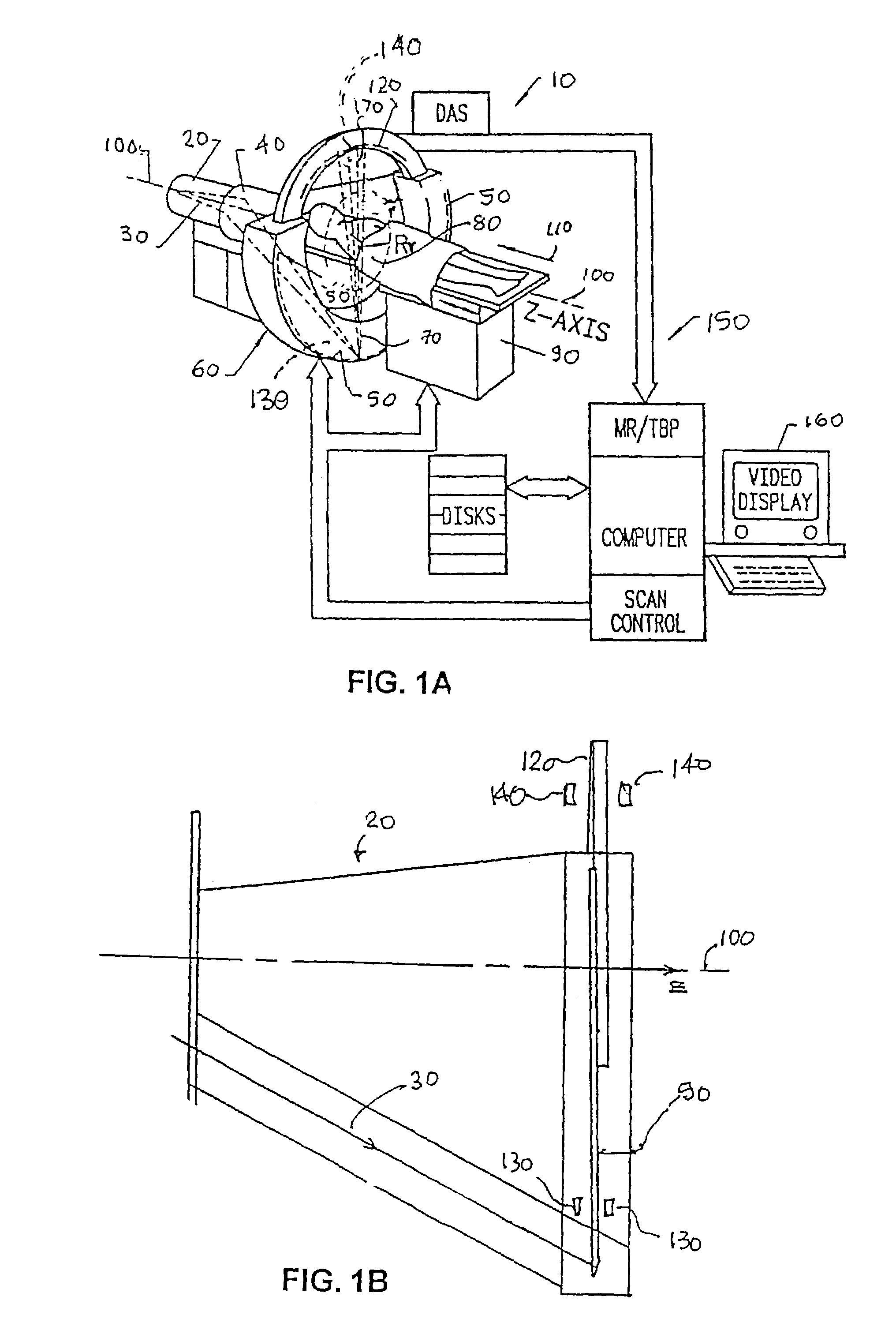
[0032]FIG. 1A depicts a scanning electron beam computed tomography (CT) system 10 according to the present invention. System 10 includes a vacuum housing chamber 20 wherein an electron beam 30 is generated and caused by a beam optics assembly 40 to scan a circular target 50 located within chamber 20's front lower portion 60. Upon being struck by the electron beam, which typically scans 210° or so, the target emits a moving fan-like beam of X-rays 70 that pass through a region of a subject 80 (e.g., a patient or other object) within the reconstruction radius Rr. Patient or object 80 typically lies on a couch 90 that is movable along the system z-axis 100 at a chosen velocity, as indicated by arrow 110. These rays then register upon a region of a detector array 120 located generally diametrically opposite. System 10 typically includes a collimator system that includes collimator elements 130 adjacent target 50, and collimator-elements 140 adjacent detector array 120. The detector arra...


PUM


Abstract

A scanning electron beam computed tomographic system eliminates axial offset between target and detector by disposing the target, collimator, and detector such that active portions of the target and detector are always diametrically opposite each other. This result is achieved by providing a helical target, collimator, and detector, or by providing planar target, collimator, and detector components that are inclined relative to the vertical axis such that active portions of the target and detector are always diametrically opposite each other. Either configuration eliminates cone beam error and the necessity to correct for same. Further, the system can provide multi-slice scanning of an object that is in constant motion at a critical velocity, without having to interpolate data. Conventional helical scanning may still be undertaken. Detector elements can be disposed axially to improve signal / noise ratio and to produce a cone beam cancellation effect.

Description

CROSS REFERENCE TO RELATED APPLICATIONS[0001]This is a continuation of Ser. No. 09 / 728,481 filed Nov. 28, 2000 now U.S. Pat. No. 6,735,271.FIELD OF THE INVENTION[0002]The present invention relates generally to scanning electron beam computed tomography X-ray systems, and more particularly to eliminating cone beam error in images produced by such systems, and thus the need to correct for such error, and to providing such systems with an option to make multi-slice scanning of moving objects without requiring that acquired data be interpolated.BACKGROUND OF THE INVENTION[0003]A century ago, mathematician J. Radon demonstrated that a two-dimensional slice of a three-dimensional object may be reproduced from the set of all of its projections. Computed tomography (CT) X-ray systems generate a set of X-ray beam projections through an object to be examined. The resultant detected X-ray data are computer processed to reconstruct a tomographic image-slice of the object.[0004]Conventional CT s...

Claims


Application Information

Patent Timeline
IPC IPC(8): H05G1/60A61B6/03G01N23/04G06T11/00G21K1/06
CPCA61B6/032A61B6/4028A61B6/4085G01N23/046G21K1/06A61B6/027G06T11/005G01N2223/612G06T2211/428G01N2223/419
Inventor RAND, ROY E.HARMAN, JONATHANBOYD, DOUGLAS P.
Owner GE MEDICAL SYST GLOBAL TECH CO LLC
Learn More