Methods and apparatus for dynamical helical scanned image production

a dynamical helical scan and image technology, applied in tomography, applications, instruments, etc., can solve the problems of not providing the capability of known scanning ct imaging systems to allow for the pitch of a helical scan to vary, and the known scanning ct imaging systems do not provide this capability

Active Publication Date: 2005-12-20
GE MEDICAL SYST GLOBAL TECH CO LLC
View PDF24 Cites 21 Cited by
  • Summary
  • Abstract
  • Description
  • Claims
  • Application Information

AI Technical Summary

Benefits of technology

[0008]Various configurations of the present invention allow an exact, or nearly exact table location to be used in the image reconstruction process. These configurations are useful, for example, for varying the velocity or acceleration of a patient during a helical scan to meet clinical requirements. Applications of the invention include, but are not limited to, cardiac scanning applications and perfusion applications. Moreover, the ability to start a helical scan during acceleration and / or deceleration of the patient table can be provided when scanning at a fixed helical pitch.

Problems solved by technology

Known scanning computed tomography (CT) imaging systems do not allow for the pitch of a helical scan to vary during a scan.
Known scanning CT imaging systems do not provide this capability.

Method used


Image

  • Methods and apparatus for dynamical helical scanned image production
  • Methods and apparatus for dynamical helical scanned image production
  • Methods and apparatus for dynamical helical scanned image production

Examples


Embodiment Construction

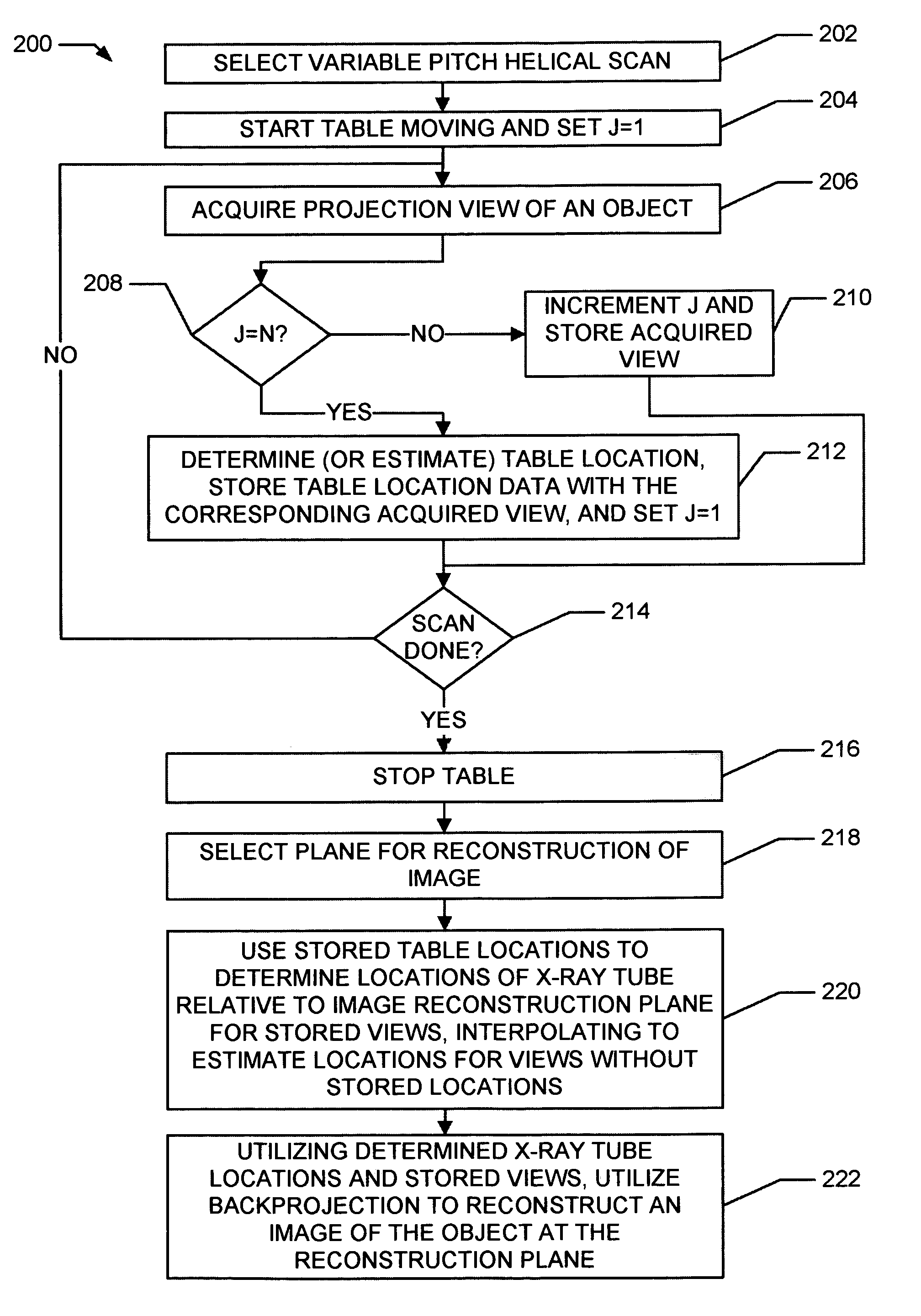
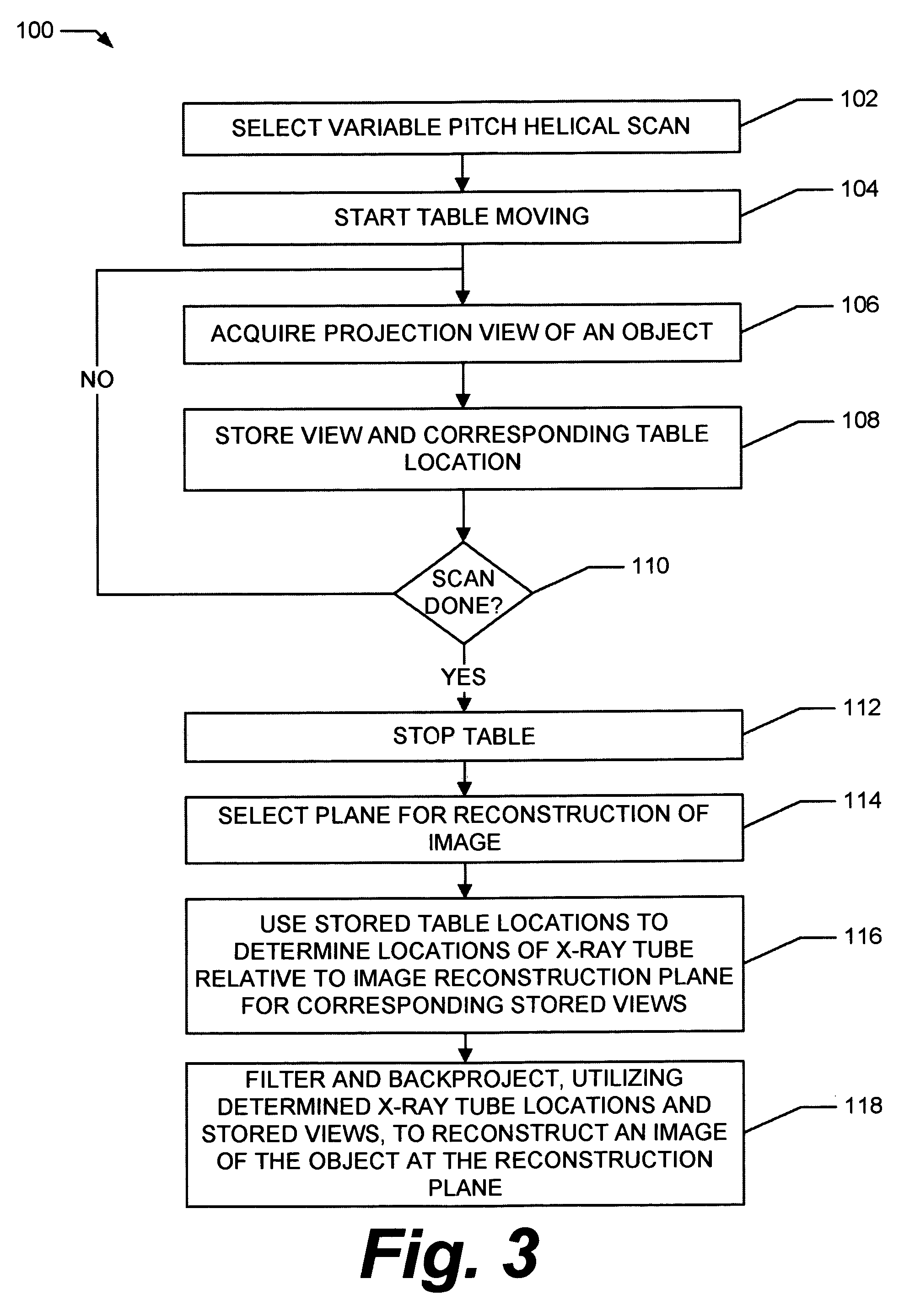
[0014]It will be appreciated that a technical effect of the configurations of the present invention described herein is the scanning and reconstruction of an object or patient utilizing a dynamical helical scan.

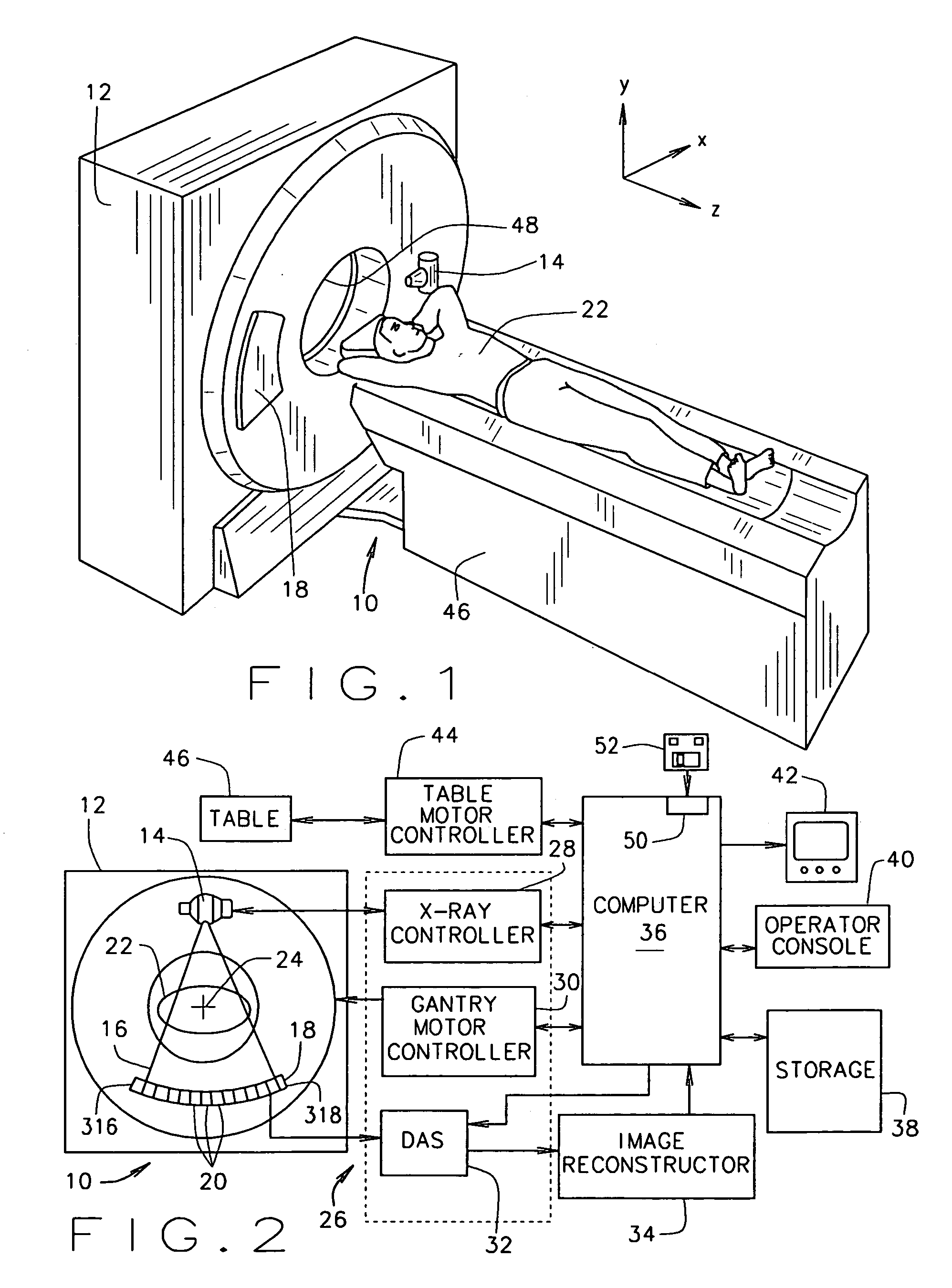
[0015]In some known CT imaging system configurations, an x-ray source projects a fan-shaped beam which is collimated to lie within an X-Y plane of a Cartesian coordinate system and generally referred to as an “imaging plane”. The x-ray beam passes through an object being imaged, such as a patient. The beam, after being attenuated by the object, impinges upon an array of radiation detectors. The intensity of the attenuated radiation beam received at the detector array is dependent upon the attenuation of an x-ray beam by the object. Each detector element of the array produces a separate electrical signal that is a measurement of the beam intensity at the detector location. The intensity measurements from all the detectors are acquired separately to produce a transmission profi...


PUM

PropertyMeasurementUnit
scanning imagingaaaaaaaaaa
computed tomographic imagingaaaaaaaaaa
weightaaaaaaaaaa

Abstract

The present invention provides a method for producing images of an object. The method includes dynamically helically scanning an object on a moving table utilizing a scanning imaging system. During the scan, projection views of the object are acquired and stored together with corresponding table locations. A plane for reconstruction of an image of the object is selected. The stored table locations are used to determine geometric variables applicable to the stored projection views; and the stored projection views are filtered and backprojected utilizing the geometrical variables to reconstruct an image of the object at the reconstruction plane.

Description

BACKGROUND OF THE INVENTION[0001]This invention relates generally to scanning imaging systems, and more particularly to the production of images by scanning imaging systems having a table that is capable of moving at a variable rate during a scan of an object or a person.[0002]Known scanning computed tomography (CT) imaging systems do not allow for the pitch of a helical scan to vary during a scan. Instead, the helical pitch (i.e., table speed) is held constant during a CT scan. To achieve constant table speed, the table is positioned a distance away from a desired starting location and accelerated to a desired speed. During the acceleration, the x-ray beam is not turned on and no data is acquired. When the table reaches the desired speed and passes the starting location, the beam is turned on and data acquisition starts.[0003]Faster and higher performance scanning CT imaging systems allow for increased clinical applications. Several new clinical applications in the cardiac and perf...

Claims


Application Information

Patent Timeline
Patent Type & Authority Patents(United States)
IPC IPC(8): A61B5/055A61B6/03G01N23/04G06T1/00
CPCA61B5/055A61B6/032G01N23/046A61B6/027Y10S378/901G01N2223/419G01N2223/612A61B5/704
Inventor HSIEH, JIANGWILLIAMS, EUGENE CLIFFORDTOTH, THOMAS LOUIS
Owner GE MEDICAL SYST GLOBAL TECH CO LLC
Why Eureka
Try Eureka