
Mechanical pencil comprising a retractable lead guide

Inactive Publication Date: 2007-07-26
SOC DITE SOC BIC
View PDF4 Cites 2 Cited by
  • Summary
  • Abstract
  • Description
  • Claims
  • Application Information

AI Technical Summary

Problems solved by technology

However, besides the geometrical complexity and the difficulty of fine tuning the frictional forces, the fact that these fins are necessarily made of a plastic material whose surface rigidity is greater than that of a rubber-type material means that there are limited co

Method used


Image

  • Mechanical pencil comprising a retractable lead guide
  • Mechanical pencil comprising a retractable lead guide
  • Mechanical pencil comprising a retractable lead guide

Examples


Example

[0036] In the various figures, identical reference denote identical or similar parts.

DETAILED DESCRIPTION OF DRAWINGS

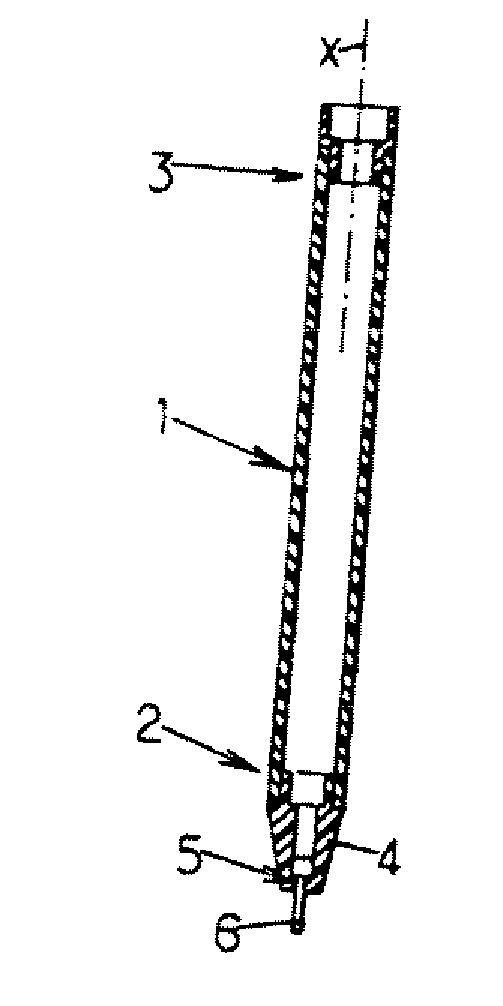
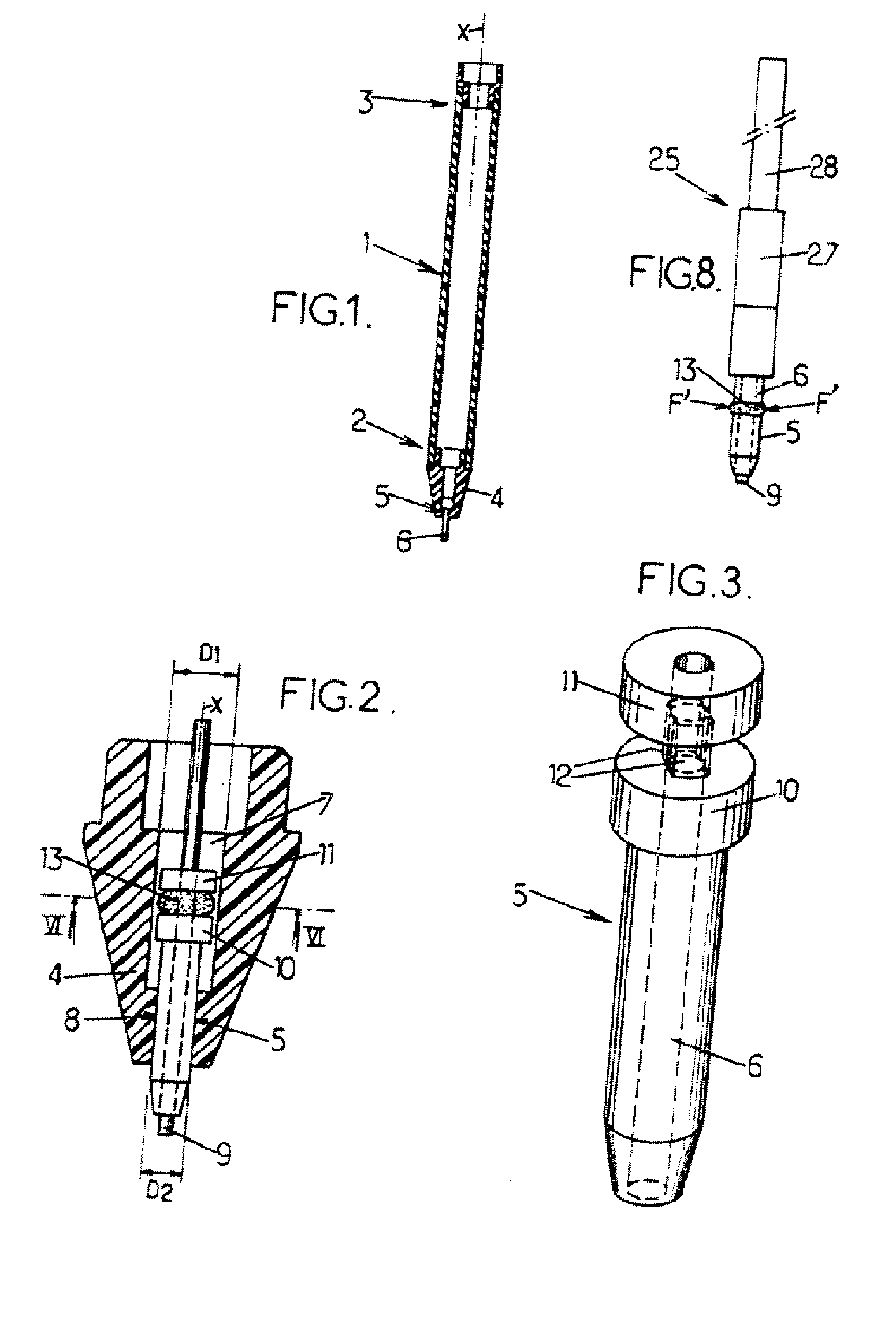
[0037] An example of a mechanical pencil according to the embodiment of the present invention is shown in FIG. 1. It has a cylindrical body 1 extending longitudinally along an axis X. This body 1 has a forward end 1 and a rear end 3. An endpiece 4 is mounted at the forward end 2. This endpiece 4 comprises a lead guide 5. This lead guide 5 comprises a conduit 6 designed to guide a lead translationally along the axis X and protect it as it emerges from the endpiece 4.

[0038] Hereinafter, the mechanical pencil according to the embodiment of the present invention will not be described in detail except as relate to its endpiece 4 and its lead guide 5 because the rest of the lead-advancing mechanism (which is not shown), in the mechanical pencil, can be of any type known to those skilled in the art.

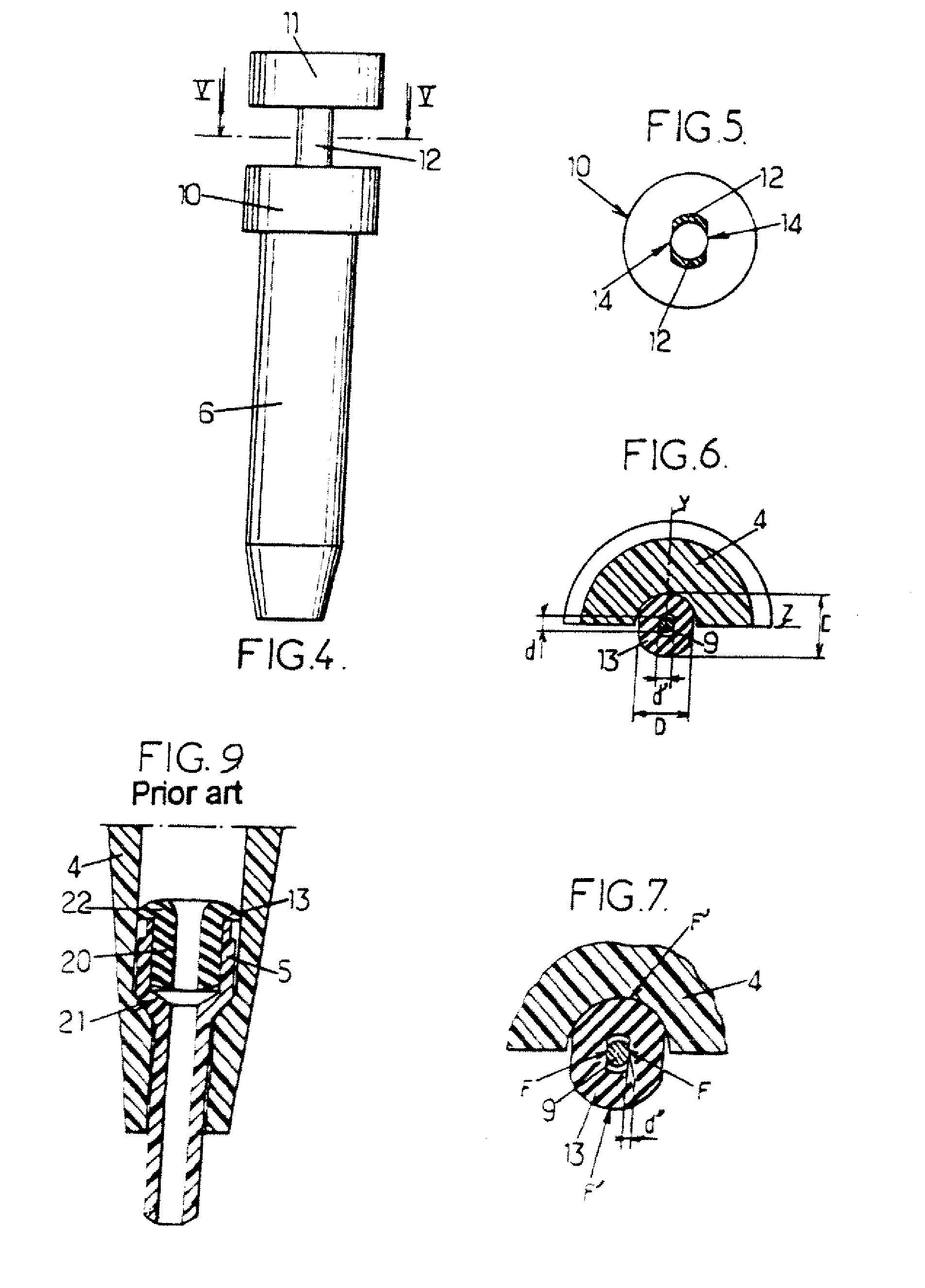
[0039] As shown in FIG. 2, the endpiece 4 is essentially in the shape of ...


PUM


Abstract

A mechanical pencil that includes a body extending longitudinally along an axis X between a forward writing end and a rear end, and an endpiece situated at the forward end and a lead guide that can be retracted into the endpiece that includes a conduit for the passage of a lead. The mechanical pencil also includes a lead brake made of an elastically deformable material connected to the lead guide.

Description

[0001] This application is a national stage application of PCT / FR-05 / 000412, filed on Feb. 22, 2005.FIELD OF INVENTION [0002] The embodiments of the present invention relate to mechanical pencils comprising a retractable lead guide. BACKGROUND OF INVENTION [0003] More particularly, the embodiments of the present invention relate to a mechanical pencil of the type comprising: [0004] a body extending longitudinally along an axis X between a forward writing end and a rear end, [0005] an endpiece situated at the forward end, [0006] a lead guide that can be retracted into the endpiece and comprises a conduit for the passage of a lead and for its guidance in translational movement along the axis X, and [0007] a lead brake made of an elastically deformable material connected to the lead guide, the lead brake comprising at least one region of friction between the lead and the lead brake to limit the movement of the lead in the lead guide, and at least one region of friction between the endp...

Claims


Application Information

Patent Timeline
IPC IPC(8): B43K21/22B43K21/027
CPCB43K21/22B43K21/027B43K21/16
Inventor FRANCK, ROLIONFREDERIC, DUCHESNEBOUVERESSE, JEANNE-ANTIDE
Owner SOC DITE SOC BIC
Learn More