
Method, system and computer program for testing a command line interface of a software product

a command line interface and software product technology, applied in the field of information technology, can solve the problems of time-consuming and laborious work required to design the test process, heavy human intervention in programming, and repetitive and tedious work

Inactive Publication Date: 2007-07-26
IBM CORP
View PDF8 Cites 24 Cited by
  • Summary
  • Abstract
  • Description
  • Claims
  • Application Information

AI Technical Summary

Benefits of technology

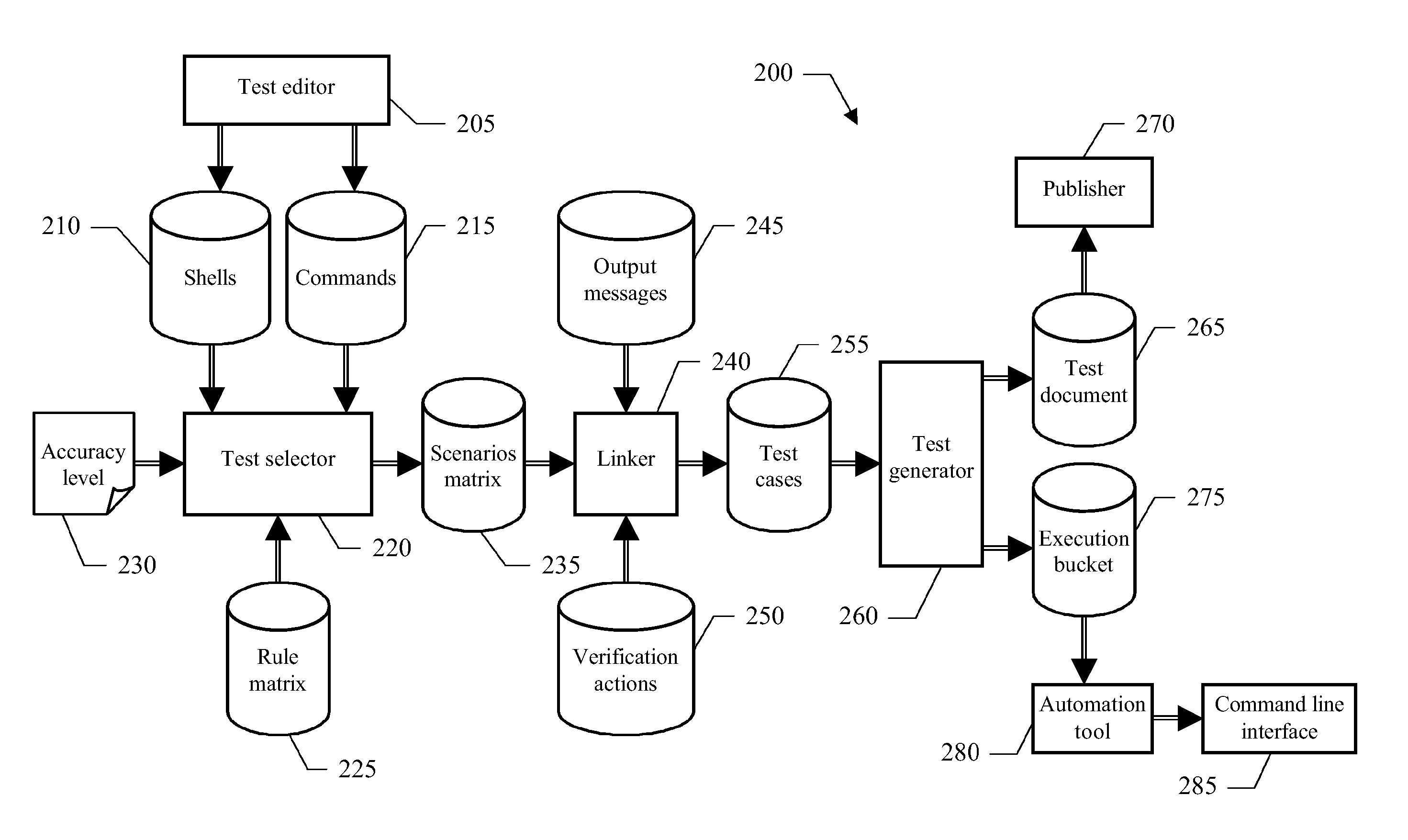
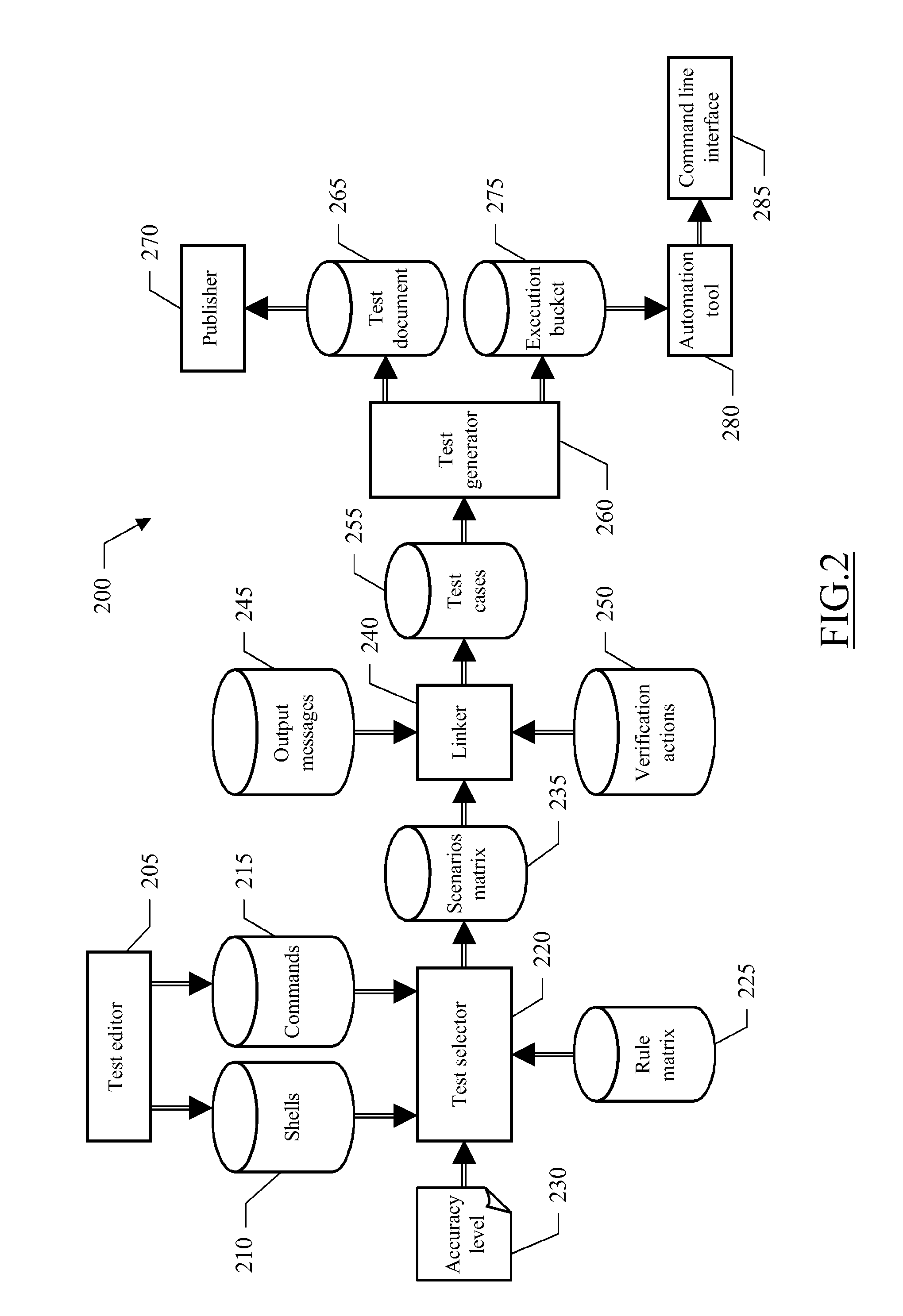
[0011] Particularly, an aspect of the invention provides a method for testing a command line interface of a software product. The method starts with the step of providing a definition of a set of (one or more) commands of the interface; each command requires a set of arguments (down to none), with each argument that has a set of (one or more) properties. Examples of those properties are a data type (such as number, string, or date) and / or other options (such required, optional or positional). The method also involves providing a definition of a set of (one or more) allowable conditions and non-allowable conditions for each property. Examples of those conditions are a right / wrong format, a required argument that is missing, and the like; preferably, the conditions of some properties are based on a formal specification of corresponding constraints (such as an acceptable range or pattern). The method continues by generating a set of (one or more) test scenarios (i.e., a scenarios matrix). The test scenarios include the invocation of the commands with their arguments that are assigned according to selected ones of the conditions. In a preferred embodiment, the selected conditions are determined as a function of a desired accuracy level; moreover, in the above-mentioned example this involves resolving the formal specification of each constraint into its actual value (included in the definition of the corresponding command). A set of test cases is now generated by associating an expected result to each test scenario. For example, it is possible to exploit an imported list of the output messages of the interface; in addition, it is also possible to indicate verification actions to the performed for checking the successful completion of the test scenario. The method ends by causing the execution of the test cases. In an embodiment of the invention, this result is achieved by generating an execution bucket for an automation tool; in addition or in alternative, it is possible to generate a test document for the manual execution of the test cases.

Problems solved by technology

Very often, the execution of the test cases as well is performed manually; however, even when an automation tool is available, its programming requires a heavy human intervention.
The problem is particular acute in large software products.
In any case, the work required to design the test process is time consuming, repetitive and tedious; likewise, its execution is a long and boring activity.
Moreover, the quality of the test process strongly depends on the skill of the test manager; therefore, the obtained results are not repeatable and prone to errors.
The same document (which is intended to describe the test cases) is not well suited to convey and / or share the desired information, and does not allow an objective analysis of the test process.
All of the above adversely affects the cost and the quality of the test process; this hinders its extensive application, with a negative repercussion on the reliability of the software products.

Method used


Image

  • Method, system and computer program for testing a command line interface of a software product
  • Method, system and computer program for testing a command line interface of a software product
  • Method, system and computer program for testing a command line interface of a software product

Examples


Embodiment Construction

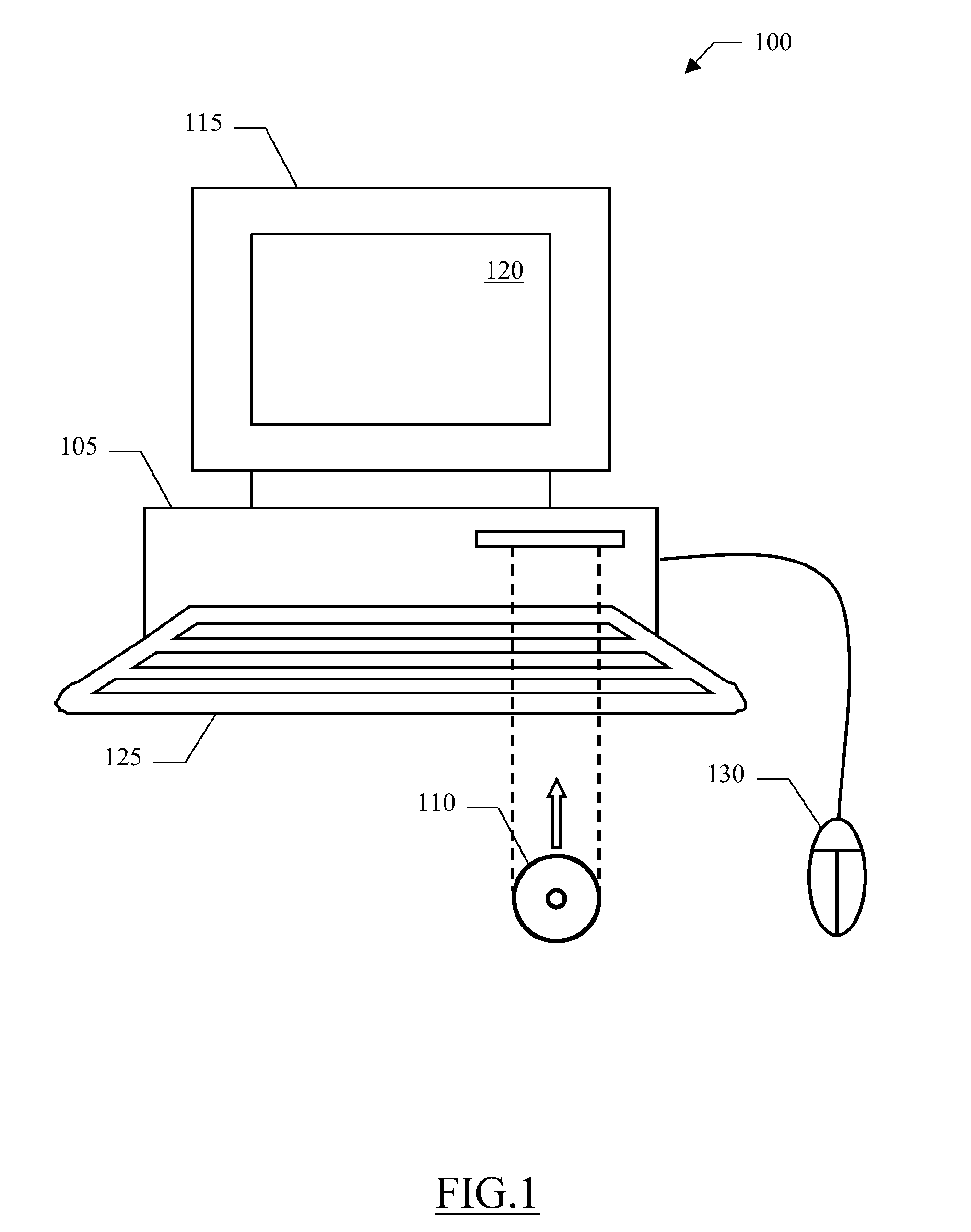
[0018] With reference in particular to FIG. 1, a computer 100 (for example, a PC) is shown. The computer 100 includes a central unit 105, which houses the electronic circuits controlling its operation (such as a microprocessor and a working memory). The computer 100 is also provided with a hard-disk and a drive for CD-ROMs 110. A monitor 115 is used to display images on a screen 120. Operation of the computer 100 is controlled by means of a keyboard 125 and a mouse 130, which are connected to the central unit 105 in a conventional manner.

[0019] The computer 100 may be used to test software products (either operating systems or application programs). More specifically, each software product provides a Command Line Interface (CLI) to end-users for accessing its services. In this case, the end-users interact with the software product through lines of textual commands; the commands are provided from the keyboard (in an interactive way) or from a script file (in a batch mode). In the fi...


PUM


Abstract

A solution (200) for facilitating the test of a command line interface (CLI) of a software product is proposed. For this purpose, the process is divided into two phases. The first phase relates to the generation of a scenarios matrix (235). This result is achieved by defining each command of the CLI (205-215), and more specifically its arguments and the corresponding properties (such as their acceptable ranges, patterns and / or option choices); the test activity is defined by specifying a desired accuracy level (230) of the test process. It is then possible to generate (220) the scenarios matrix automatically, by selecting (according to the desired accuracy level) predefined rules specifying happy paths and errors cases for each property. A second phase relates to the generation of corresponding test cases (255). For this purpose, an expected result (i.e., an output message with optional verification actions) is associated (240-250) with each test scenario in the respective matrix. This allows creating a test document (265) for the manual execution of the test process and / or a bucket (275) for its automatic execution by an automation tool (280).

Description

FIELD OF THE INVENTION [0001] The present invention relates to the information technology field. More specifically, the present invention relates to the test of a command line interface of a software product. BACKGROUND ART [0002] The test of software products (to verify their correctness, completeness and quality) is a very critical process. The execution of a test process generally requires performing selected operations and then verifying whether the software product behaves as expected. For this purpose, each tester interacts with the software product by means of a corresponding interface, which may be of the command line type or of the graphical type; particularly, in a Command Line Interface (CLI) the commands with respective arguments are provided in a textual format (from a keyboard or a script file), while in a Graphical User Interface (GUI) the commands are issued by manipulating images on a monitor with a pointer (of a mouse). The CLI is very powerful and allows performin...

Claims


Application Information

Patent Timeline
Patent Type & Authority Applications(United States)
IPC IPC(8): G06F11/00
CPCG06F11/3688
Inventor ROSSI, RICCARDOSEGHETTI, GIANLUCA
Owner IBM CORP
Learn More