
Solid state light source

a light source and solid state technology, applied in the direction of instruments, lighting support devices, cycle equipment, etc., can solve the problems of halogen lamps consuming 150 watts of power, generating a tremendous amount of heat, and the light source of halogen lamps is not sealed

Inactive Publication Date: 2007-08-02
LED PIPE
View PDF80 Cites 68 Cited by
  • Summary
  • Abstract
  • Description
  • Claims
  • Application Information

AI Technical Summary

Benefits of technology

"The present invention is a modular light source that includes a housing, LED elements, and a controller. The controller can sequentially or intermittently pulse the LED elements, and may over-drive them with a current in excess of several times the continuous forward rating. The housing is a closed, waterproof tubular metal member that may include a power source. The light source may be portable, such as a flashlight or a bicycle light, or used in machine vision. It may include a plurality of colors of LED elements and a controller to evaluate the power source and control the LED array accordingly. The controller may accept external strobe signals. The technical effects of the invention include a modular design, high-intensity light output, and versatility in LED element size and control."

Problems solved by technology

However, the typical halogen source suffers several shortcomings and was not designed for use on the factory floor.
The light from a fresh halogen lamp is brilliant; but, output declines steadily over the lamp's relatively short (typically) 1000 hour life.
In addition, a typical halogen lamp consumes 150 watts of power and generates a tremendous amount of heat.
Consequently, the typical halogen lamp light source is not a sealed, shock resistant unit because ventilation is required.
Due to these design considerations, present product offerings are housed in heavy, bulky enclosures.
While not as bright, LED technology offers features and capabilities unavailable with halogens.
However, the illumination patterns generated from these products are generally poor and uneven because the individual LED elements produce hot spots that randomized fiber optic would have eliminated.
LED light sources have been proposed in a number of areas, but have not yet adequately addressed all of the lighting criteria.

Method used


Image

  • Solid state light source
  • Solid state light source
  • Solid state light source

Examples


Embodiment Construction

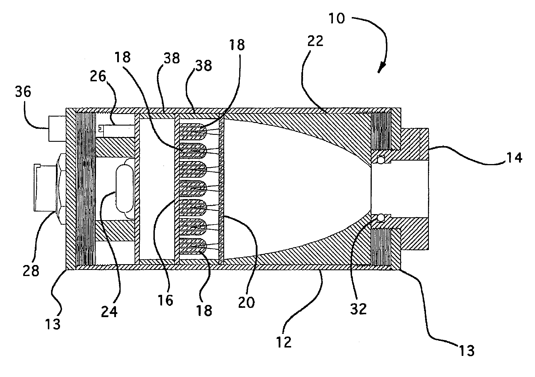
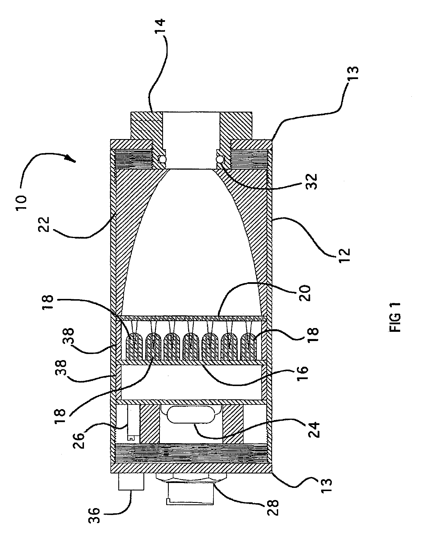
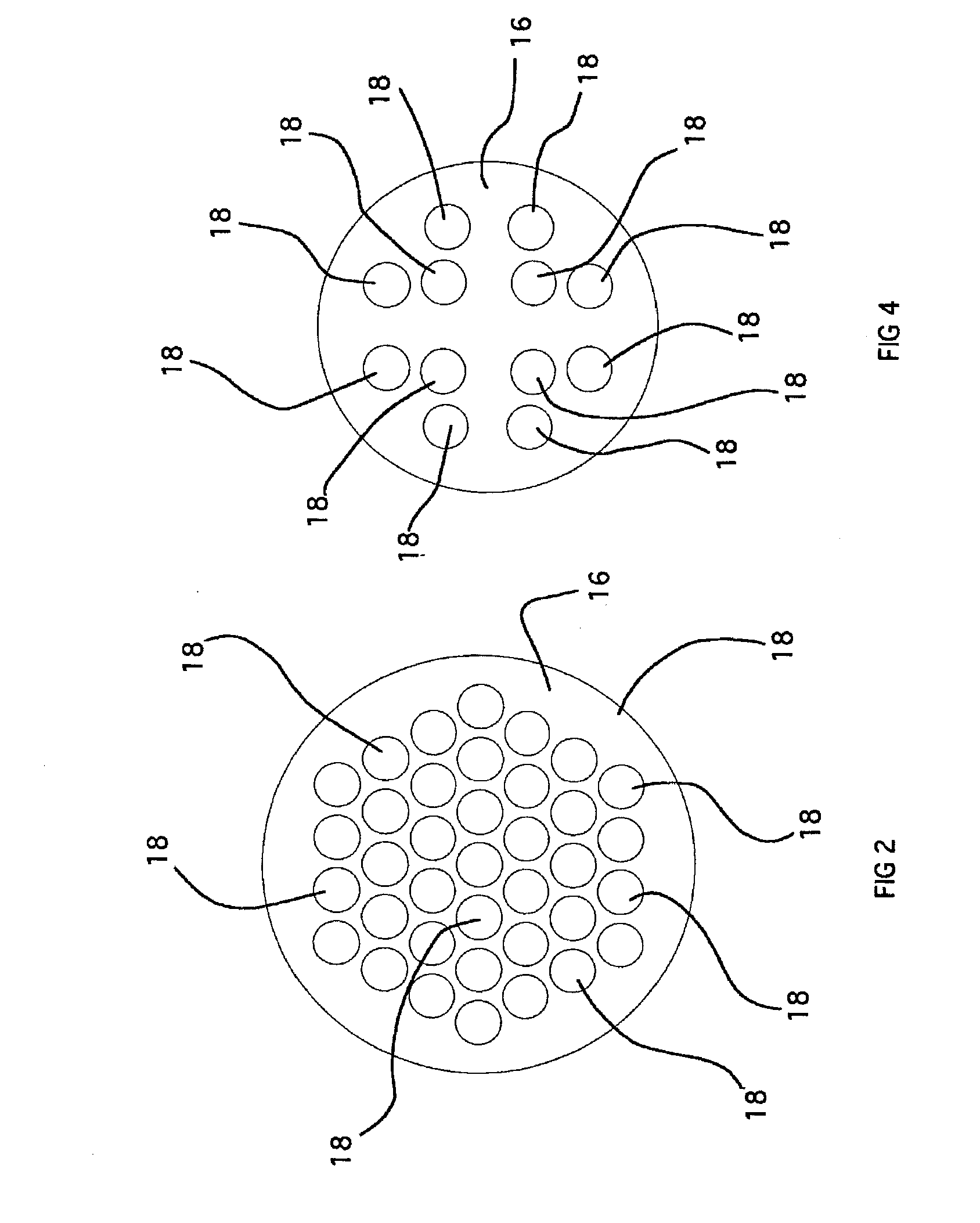
[0053] One embodiment of the present invention is shown in FIGS. 1-2. As shown in FIG. 1, the present invention is a modular light source 10 for illuminating a fiber optic bundle (not shown) such as used in machine vision illumination. The light source 10 includes a rigid, substantially closed tubular housing 12 formed of an anodized aluminium tube with threaded end caps 13 closing the threaded ends of the housing 12. Other materials, such as plastic or steel, may also be used to form the housing 12. One end cap 13 attached to the tubular housing 12 includes a conventional fiber optic bundle coupling 14 for receipt of an end of a fiber optic bundle in a conventional manner. The housing 12 can easily accommodate different couplings 14 simply by replacing the end cap 13 and coupling 14 with an end cap 13 having a different sized coupling 14, or threading a different sized coupler 14 into the end cap 13 such as may be possible with couplers 14 having a smaller inner diameter. This cons...


PUM


Abstract

A modular light source system forms a plurality of distinct light sources with a common tubular metal housing, an LED based lighting element for each light source, and a pair of end caps on opposed ends of the metal housing for each light source. Each distinct lighting source is comprised of one of the LED based lighting elements and a given pair of the end caps, whereby distinct light sources can be formed through replacement of the LED based lighting elements and the end caps.

Description

RELATED APPLICATION [0001] This application is a divisional of and claims the benefit of U.S. patent application Ser. No. 10 / 759,516 entitled “Solid State Light Source” filed Jan. 16, 2004, now U.S. Pat. No. 7,083,298, and which published as U.S. Patent Application Publication number 2004-00170014 on Sep. 2, 2004. U.S. patent application Ser. No. 10 / 759,516 is a continuation-in-part of and claims the benefit of U.S. patent application Ser. No. 10 / 263,922 entitled “Solid State Light Source” filed Oct. 3, 2002, now U.S. Pat. No. 6,957,905, U.S. patent application Ser. No. 10 / 263,922 claims the benefit of U.S. patent application Ser. No. 60 / 326,802 entitled “Solid State Light Source” Filed Oct. 3, 2001. The above identified patents and published patent application are incorporated herein by reference in their entirety.BACKGROUND OF THE INVENTION [0002] 1. Field of the Invention [0003] The present invention relates to a solid state light source, and more particularly, to a modular light...

Claims


Application Information

Patent Timeline
Patent Type & Authority Applications(United States)
IPC IPC(8): F21S13/14B62J6/02F21L4/02F21V8/00F21V21/06F21V21/088
CPCB62J6/02F21K9/00F21L4/027F21L14/023F21V2200/17F21V21/06F21V21/0824F21V21/0885F21Y2101/02F21V15/015F21Y2115/10B62J6/029
Inventor PRITCHARD, DONALD V.MAGISKE, WILLIAM J.
Owner LED PIPE
Learn More