
Vehicle lighting device

Inactive Publication Date: 2007-08-02
KOITO MFG CO LTD
View PDF6 Cites 15 Cited by
  • Summary
  • Abstract
  • Description
  • Claims
  • Application Information

AI Technical Summary

Benefits of technology

[0009]One or more embodiments of the present invention provide a vehicle lighting device for which, without increasing the device size, the interposition of a darker portion between reflected light and light directly emitted by an LED, to the front and downward, is prevented, and the view to the front is improved.
[0027]According to one or more embodiments of the invention, the vehicle lighting device includes the second reflective portion, which reflects light at a lower level than light is reflected by the first reflective portion. Thus, light reflected by the second reflective portion can be directed toward the dark portion that is interposed between the light reflected by the first reflective portion and the light component that is directly emitted to the front and downward by the LED, so that throughout the irradiation range the light appears to be contiguous, and the view to the front is improved. Especially for the headlamps and auxiliary headlamps of a two-wheeled vehicle, since near a driver, at the front of the irradiation range, the visible area provided for the driver is large, a contiguous irradiation range can effectively improve the view to the front.
[0028]Furthermore, according to one or more embodiments of the invention, the first reflective portion and the second reflective portion are integrally formed, and the second reflective portion is formed near the upper end of the reflective face. Therefore, when the second reflective portion that transmits reflected light downward is formed on the reflective face, only a small segment of a light component is blocked by parts (e.g., the extension component) positioned in front of the reflective portion, and lighting is efficiently performed. Further, when the reflective portions are integrally formed, a gap (light leakage) does not occur, and the lighting efficiency is increased.
[0029]According to one or more embodiments of the invention, the first reflective portion is formed of a plurality of reflective segments. Of these reflective segments, connection reflective segments are prepared contiguously to either side of the central reflective segment located below the LED so that at least one reflective segment is connected to one of sides of the central reflective segment, and the second reflective portion is contiguously formed with the central reflective segment. Therefore, the second reflective portion is located near the upper end of the central reflective segment, which is nearest the LED and from which diffused light emission is enabled bilaterally and symmetrically. As a result, reflected light can be accurately emitted within a desired irradiation range.
[0030]Furthermore, according to one or more embodiments of the invention, the vehicle lighting device further comprises: the PES lamp unit, which includes the second LED that emits light upward, the third reflective portion, the linear light blocking portion and the projection lens, and the first LED and the second LED that are located on the upper face and the lower face of the horizontally arranged light source holder. Thus, a light distribution pattern having an accurate cut line can be formed. Further, since the two LEDs are fixed to one light source holder, and the first LED is located at the rear of the projection lens, the individual optical components can be compactly assembled, and a reduction if the size of the lighting device is possible. In addition, since the first LED can be hidden by the projection lens, almost no internal portion is visible directly from the front, and an improved design can be provided.
[0031]Moreover, according to one or more embodiments of the invention, since the first, the second, and the third reflective portions are integrally formed, the number of components and the manufacturing costs can be reduced, and further downsizing can be obtained.

Problems solved by technology

Thus, the spatial usage efficiency is low, and the size of such a lighting device is increased.

Method used


Image

  • Vehicle lighting device
  • Vehicle lighting device
  • Vehicle lighting device

Examples


Embodiment Construction

[0047]A vehicle lighting device according to the one or more embodiments of the present invention will now be described with reference to the drawings.

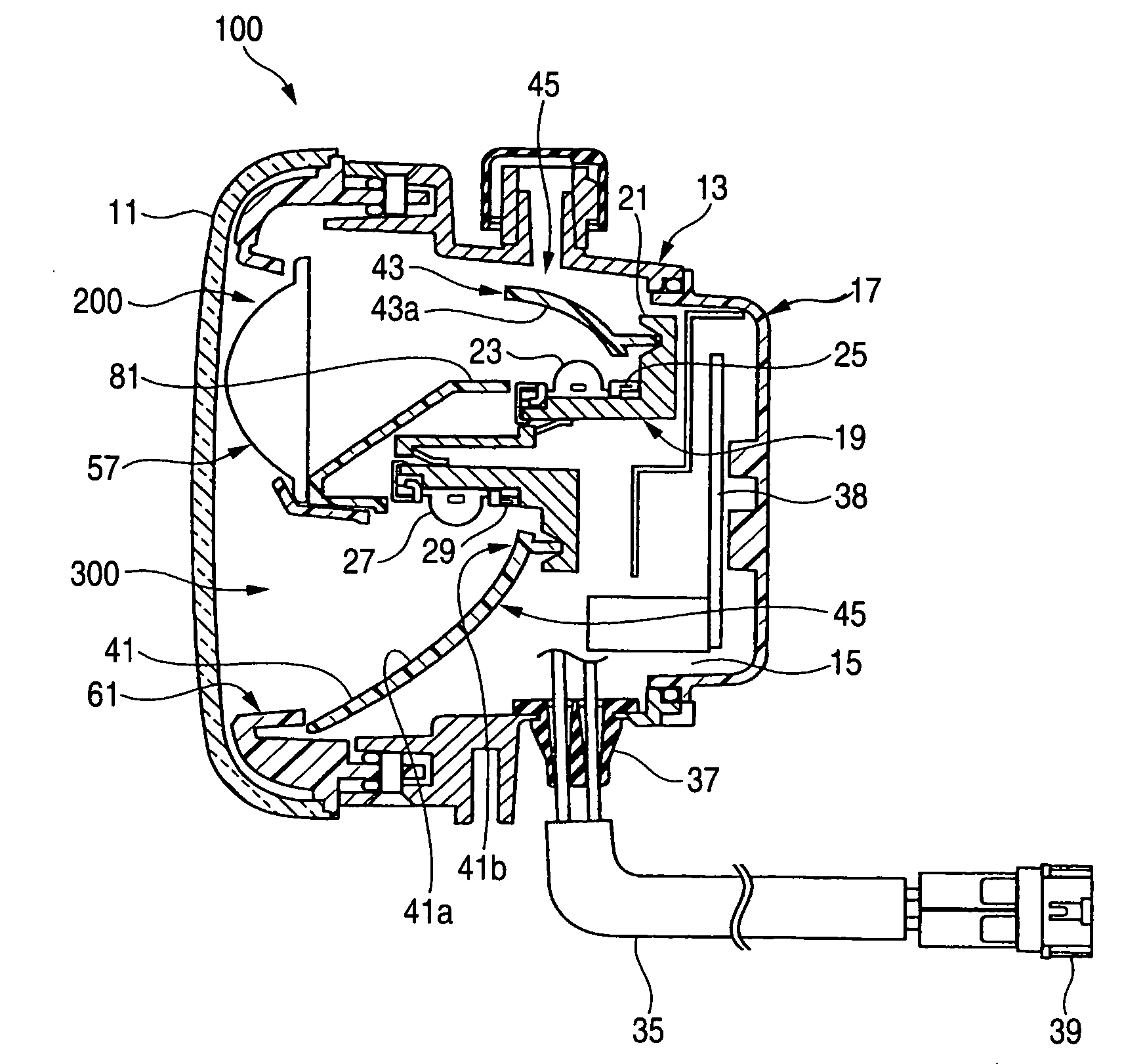
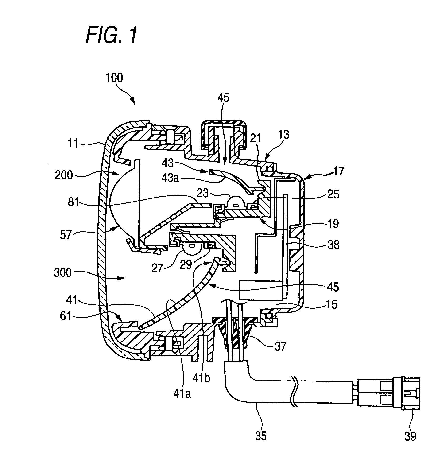
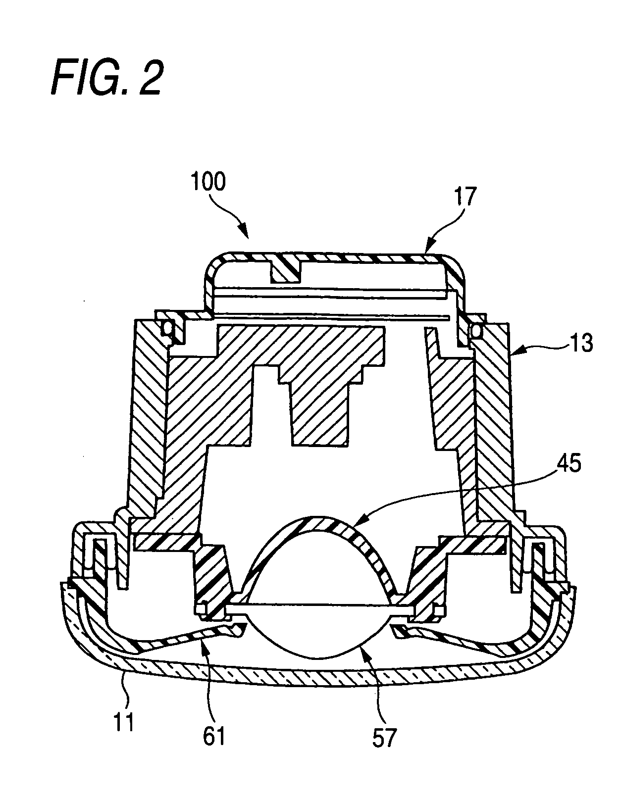
[0048]FIG. 1 is a vertical cross-sectional view of a vehicle lighting device according to one embodiment. FIG. 2 is a transverse cross-sectional view of the vehicle lighting device in FIG. 1. FIG. 3 is an exploded perspective view of the vehicle lighting device in FIG. 1. FIG. 4 is an exploded perspective view of a light source holder. FIG. 5 is a side view of a first reflective portion. FIG. 6 is a front view of the first reflective portion.

[0049]As shown in FIGS. 1 and 3, for a vehicle lighting device 100, a lamp unit 200, which is a PES lamp unit, and a lamp unit 300, which is a reflection type lamp unit, are respectively arranged at the top and bottom of a lamp chamber that is formed of a transparent, light transmitting cover 11, and a lamp body 13.

[0050]An opening 15 is formed in the rear end of the lamp body 13, and a watertight...


PUM


Abstract

A vehicle lighting device includes a reflection type lamp unit including a first LED that emits light downward; and a reflective face that reflects part of the light emitted by the first LED outward to the front of the vehicle lighting device. Part of the light emitted by the first LED is output, as directly emitted light, directly to the front of the vehicle lighting device. The reflective face includes a first reflective portion that reflects light as vertically almost parallel light and as horizontally diffused light, and a second reflective portion that reflects light below the light reflected by the first reflective portion and above the directly emitted light.

Description

BACKGROUND OF INVENTION[0001]1. Field of the Invention[0002]The present invention relates to a vehicle lighting device that includes a lamp unit for which a semiconductor light emitting device is employed as a light source.[0003]2. Background Art[0004]Recently, a light emitting diode (LED) lamp was developed. The LED lamp is characterized in that it provides increased luminance, for which only a small consumption of power is required, and is regarded as a next-generation vehicle light source. As shown in FIG. 13, for example, a headlamp for a vehicle disclosed in patent document 1 has a reflection type lamp unit 1 that includes: a semiconductor light emitting device (LED) 3, which constitutes a light source; and a reflector 5, which is disposed forward below the LED 3.[0005]According to patent document 1, the reflector 5 has a reflective face 5a, having the shape of a parabolic cylinder, from which astigmatic foci FL are horizontally extended. At the two sides of the reflective face...

Claims


Application Information

Patent Timeline
IPC IPC(8): F21V7/00
CPCF21S48/1159F21Y2101/02F21S48/1163F21Y2115/10F21S41/155F21S41/148
Inventor TATSUKAWA, MASASHI
Owner KOITO MFG CO LTD
Learn More