Schema mapping specification framework

Inactive Publication Date: 2007-08-02
IBM CORP
View PDF21 Cites 14 Cited by
  • Summary
  • Abstract
  • Description
  • Claims
  • Application Information

AI Technical Summary

Benefits of technology

[0023] Advantageously, the present invention provides a schema mapping specification framework that can represent mappings between heterogeneous schema models. Further, the present invention facilitates the creation of mapping applicati

Problems solved by technology

These characteristics of known mapping tools lead to the following deficiencies and limitations.
First, there is a significant duplication of effort with regard to development

Method used


Image

  • Schema mapping specification framework
  • Schema mapping specification framework
  • Schema mapping specification framework

Examples


example

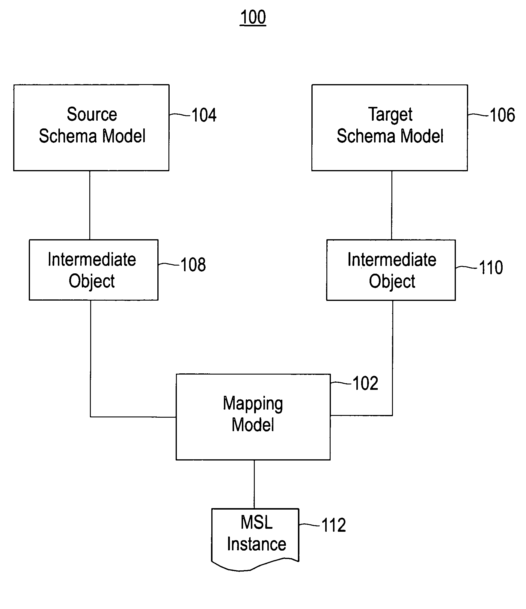
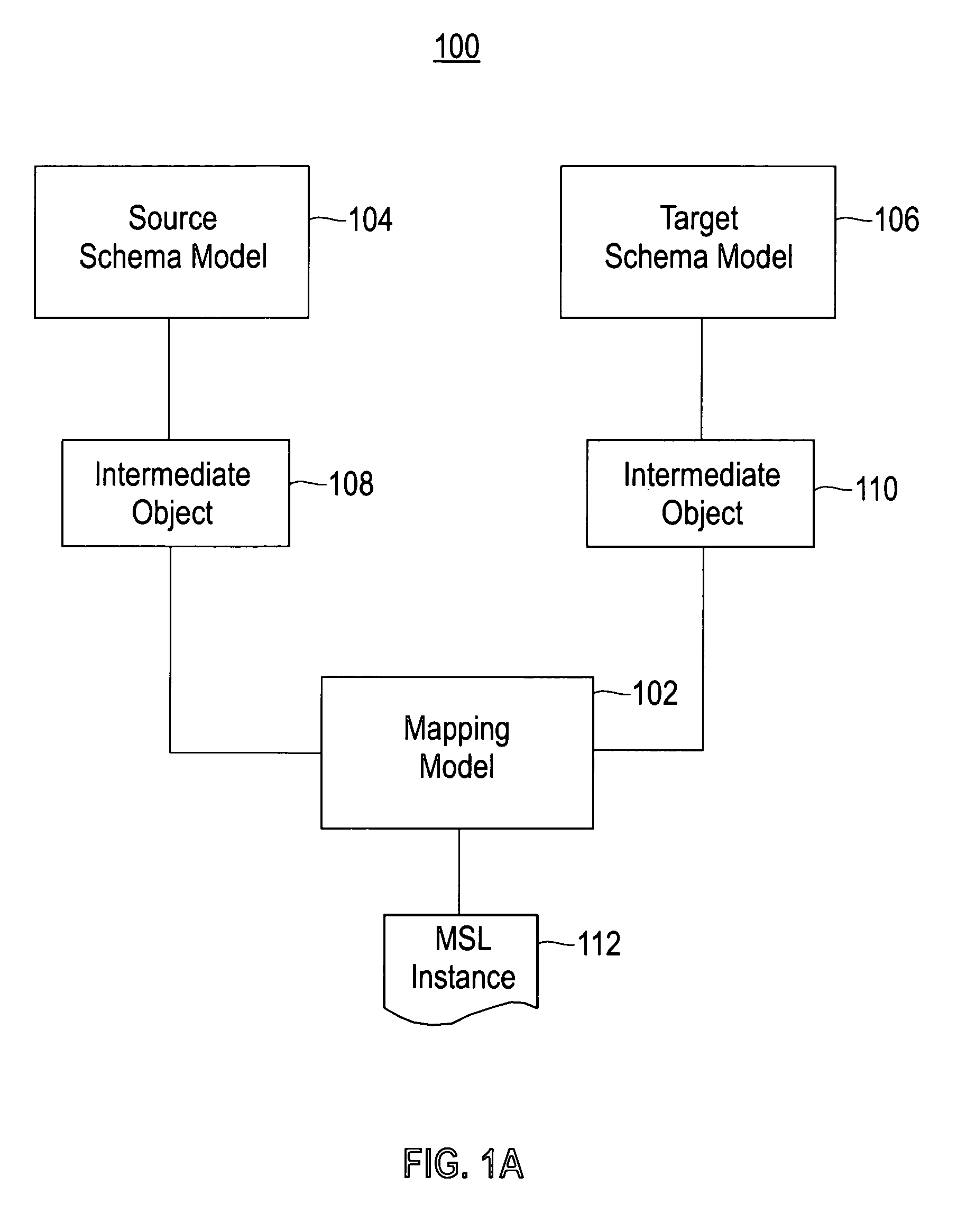
[0058]FIGS. 3A, 3B, 4A, 4B, 5A, 5B, and 6-8 illustrate an example of how Domain Resolvers are used in the schema mapping framework. Again, domain resolvers are defined in model managers 108, 110 (see FIG. 1A), which are extension points in the schema mapping framework. Two XML schemas are used in this example. Schema 300 in FIG. 3A is an example of a source schema, which is a serialized version of source schema model 104 of FIG. 1A. Schema 350 in FIG. 3B is an example of a target schema, which is a serialized version of target schema model 106 of FIG. 1A. When the source and target schemas are loaded into memory, each element in that schema becomes a node in a tree. In each of schema 300 of FIG. 3A and schema 350 of FIG. 3B, there is a top-level schema object and one or more element or type definitions under the top-level object.

[0059] The schema mapping framework provides to the user a logical representation of the source and target schemas. In this example, schema 400 of FIG. 4A ...


PUM


Abstract

A method and system for specifying, in a schema mapping framework, a mapping between a source schema and a target schema. The source and target schemas are schemas included in respective groups of registered, heterogeneous schemas. The source and target schemas may be of different types. Serialized versions of the source and target schemas include source objects and target objects, respectively. A mapping model is serialized into mapping objects that include logical references representing the source objects and logical references representing the target objects. The logical references are resolved to the source objects and target objects, thereby storing pointers to the source objects and to the target objects. After resolving the logical references, the mapping model includes the logical references and the pointers to the source and target objects.

Description

BACKGROUND OF THE INVENTION [0001] 1. Technical Field [0002] The present invention relates to a schema mapping specification framework, and more particularly to a schema mapping specification framework for representing mappings between heterogeneous schema models. [0003] 2. Related Art [0004] Each conventional software tool for mapping a source schema A to a target schema B utilizes its own model and language to express a high-level description of how A is to map to B, its own model to capture the semantic meaning of that high-level description, and its own architecture to interpret that model to generate executable code. These characteristics of known mapping tools lead to the following deficiencies and limitations. First, there is a significant duplication of effort with regard to development and maintenance of multiple mapping tools. Each mapping tool requires its own development team to build, develop and maintain the tool. Second, there is an inconsistent look and feel and beha...

Claims


Application Information

Patent Timeline
IPC IPC(8): G06F7/00
CPCG06F17/218G06F17/30914G06F17/30569G06F16/258G06F16/84G06F40/117
Inventor HERNANDEZ-SHERRINGTON, MAURICIO ANTONIOPOPA, LUCIANROTH, MARY ANNSALTER, CRAIG
Owner IBM CORP
Why Eureka
Try Eureka