Transverse wall of a combustion chamber provided with multi-perforation holes

a technology of transverse wall and combustion chamber, which is applied in the direction of combustion process, hot gas positive displacement engine plant, lighting and heating apparatus, etc., can solve the problems of substantial deterioration of deflectors and prejudicious to the service life of combustion chambers, and achieve effective and homogenous cooling of deflectors

Active Publication Date: 2007-08-09
SN DETUDE & DE CONSTR DE MOTEURS DAVIATION S N E C M A
View PDF12 Cites 7 Cited by
  • Summary
  • Abstract
  • Description
  • Claims
  • Application Information

AI Technical Summary

Benefits of technology

[0009]The object of the present invention is therefore to overcome such disadvantages by proposing a transverse wall of the combustion chamber which is in the shape of a truncated cone, so allowing for effective and homogenous cooling of the deflectors.
[0011]By creating means to force the flow of air for cooling the deflectors to flow radially around the fuel injection systems, it is possible to obtain homogenous cooling over the entire surface of the deflectors. Accordingly, any risk of deterioration of the defectors is avoided. The service life of the base of the chamber will therefore be increased.
[0013]The presence of such chicanes allows the flow of cooling air for the deflectors to be guided radially around the fuel injection systems.
[0016]The presence of these deviations in distances at the level of the respective external radial ends of the wall and the deflectors likewise allows the cooling air to flow around the fuel injection systems.

Problems solved by technology

In addition, cooling by multi-perforation of the deflectors is not homogenous, which leads to substantial deterioration of the deflectors, which is particularly prejudicial to the service life of the combustion chamber.

Method used


Image

  • Transverse wall of a combustion chamber provided with multi-perforation holes
  • Transverse wall of a combustion chamber provided with multi-perforation holes
  • Transverse wall of a combustion chamber provided with multi-perforation holes

Examples


Embodiment Construction

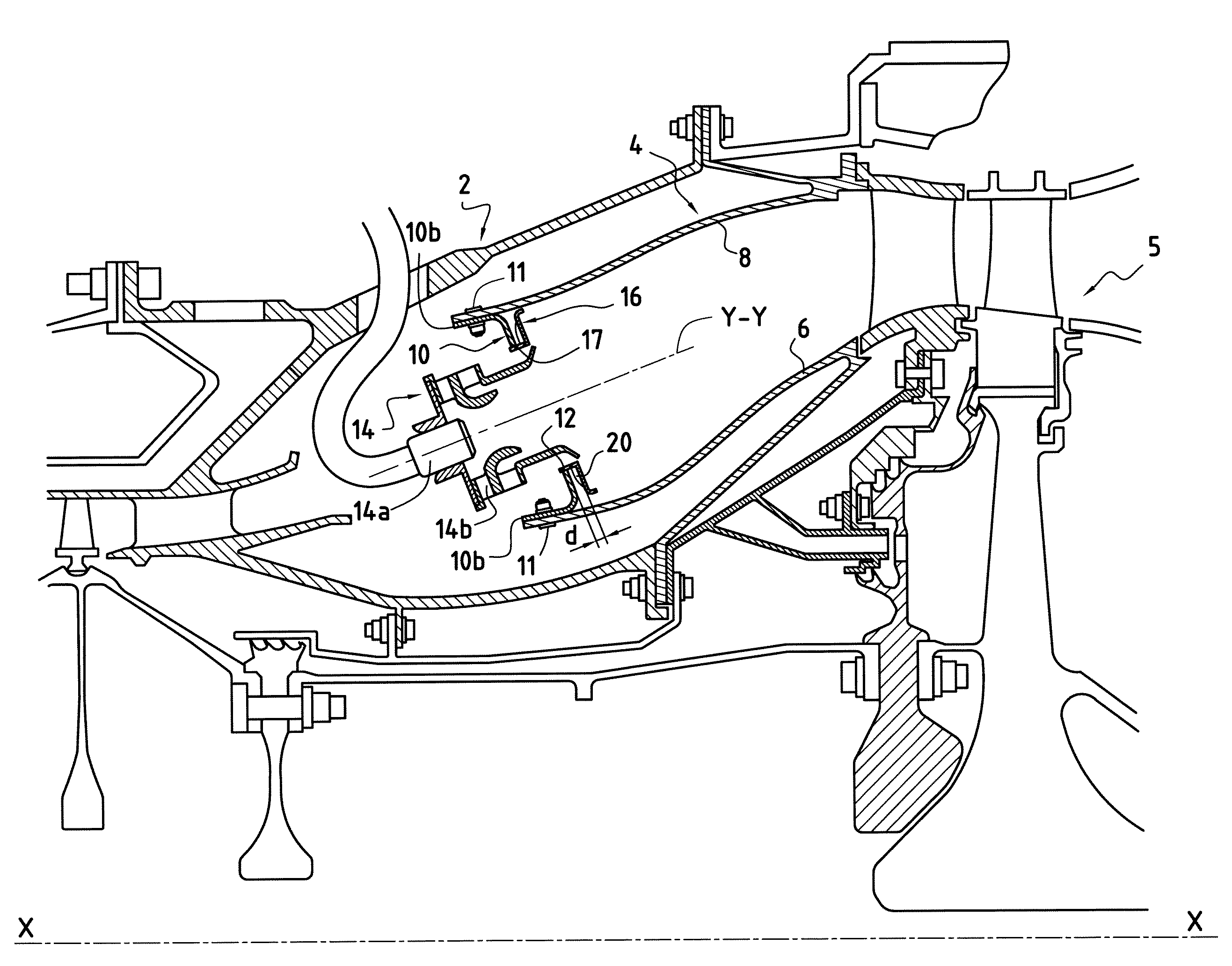
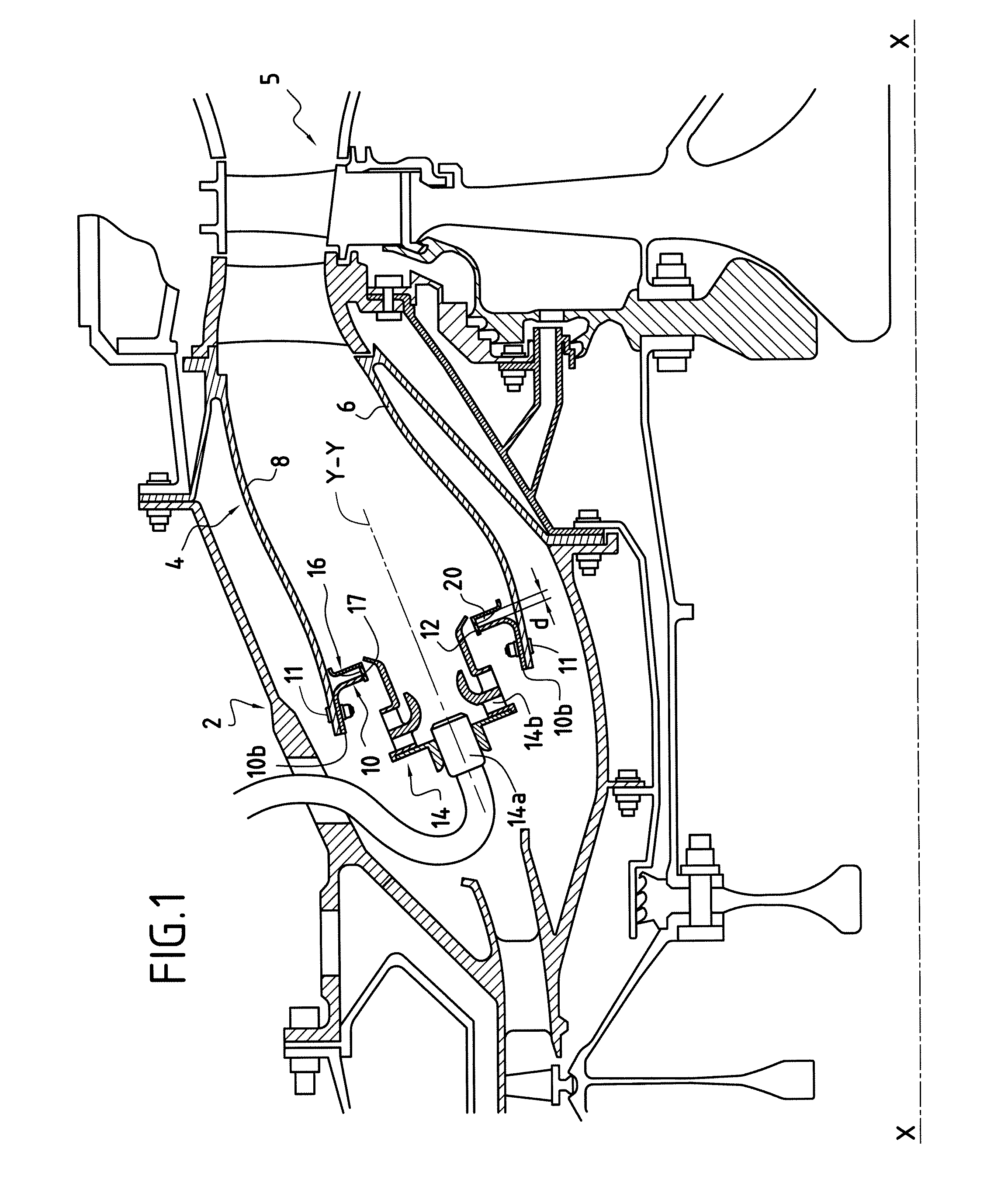
[0024]FIG. 1 shows a combustion chamber for a turbine engine. Such a turbine engine comprises in particular a compression section (not shown), in which the air is compressed before being injected into a casing of the chamber 2, then into a combustion chamber 4 mounted in its interior.

[0025]The compressed air is introduced into the combustion chamber and mixed with fuel before being combusted. The gases deriving from this combustion are then directed to a high-pressure turbine 5 arranged at the outlet of the combustion chamber 4.

[0026]The combustion chamber 4 is of the annular type. It is formed from an internal annular wall 6 and an external annular wall 8, which are connected upstream (in relation to the direction of flow of the combustion gas in the combustion chamber) by a transverse wall 10 forming the base of the chamber.

[0027]The internal wall 6 and external wall 8 of the combustion chamber extend in accordance with a longitudinal axis which is slightly inclined in relation to...


PUM


Abstract

The invention relates to an annular wall (10) intended to connect transversely longitudinal walls of an annular combustion chamber of a turbine engine. The wall (10) is essentially flat, inclined in relation to a longitudinal axis of the turbine engine, and comprises a plurality of deflectors (16), each formed by an essentially rectangular flat sheet. The deflectors are mounted on the wall and each comprise an aperture for the installation of a fuel injection system, a plurality of multi-perforation holes (18) formed in relation to the deflectors (16) around their aperture so as to allow a passage of air intended for the cooling of the deflectors, and means (20) to force the flow of air for cooling the deflectors to flow radially around the fuel injection systems.

Description

BACKGROUND TO THE INVENTION[0001]The present invention relates to the general domain of combustion chambers of a turbine engine. It relates more particularly to the wall of an annular combustion chamber which is intended to connect transversely the longitudinal walls of the said chamber.[0002]Typically, an annular combustion chamber of a turbine engine is formed from two longitudinal annular walls (one internal wall and one external wall), which are connected upstream by a transverse wall, likewise annular, forming the base of the chamber.[0003]The base of the chamber is provided with a plurality of essentially circular apertures which are distributed regularly over the whole of the circumference. Installed in these apertures are injection systems which mix the air and the fuel. This pre-mixture is intended to be burned in the interior of the combustion chamber.[0004]In order to protect the base of the chamber against the very high temperatures of the gases deriving from the combust...

Claims


Application Information

Patent Timeline
Patent Type & Authority Applications(United States)
IPC IPC(8): F23R3/50
CPCF23R3/283F23R2900/03044F23R3/10
Inventor CABOCHE, GERARD EDOUARD EMILEGAUTIER, CLAUDESANDELIS, DENIS JEAN MAURICE
Owner SN DETUDE & DE CONSTR DE MOTEURS DAVIATION S N E C M A
Why Eureka
Try Eureka