Vibrator

a vibration and spiral spring technology, applied in the field of vibrations, can solve the problems of not being able to stably obtain large vibrations using resonance, difficult to surely inform users of incoming calls, and using spiral leaf springs to achieve the effect of good linear frequency characteristics

Inactive Publication Date: 2007-08-09
CITIZEN ELECTRONICS CO LTD
View PDF2 Cites 45 Cited by
  • Summary
  • Abstract
  • Description
  • Claims
  • Application Information

AI Technical Summary

Benefits of technology

[0013] Accordingly, an object of the present invention is to provide a vibrator having good linearity in frequency characteristics and capable of surely informing a user of an incoming call when it is incorporated in a cellular phone.
[0015] In the vibrator according to the present invention, the arcuate portions of the first and second suspensions extend from the first end, which is connected to the inner ring portion, to the second end, which is connected to the outer ring portion, in the same circumferential direction as seen from one side of the axial direction. Consequently, when the vibrating member is vibrated in the axial direction, turning forces applied to the vibrating member from the arcuate portions of the first and second suspensions are opposite to each other. Therefore, rotation of the vibrating member can be substantially suppressed.

Problems solved by technology

Thus, the vibrator using a pair of spiral leaf springs 30 as stated above cannot stably obtain large vibrations using resonance.
Hence, it is difficult to surely inform a user of an incoming call when this vibrator is applied to a cellular phone.

Method used


Image

  • Vibrator
  • Vibrator
  • Vibrator

Examples


Embodiment Construction

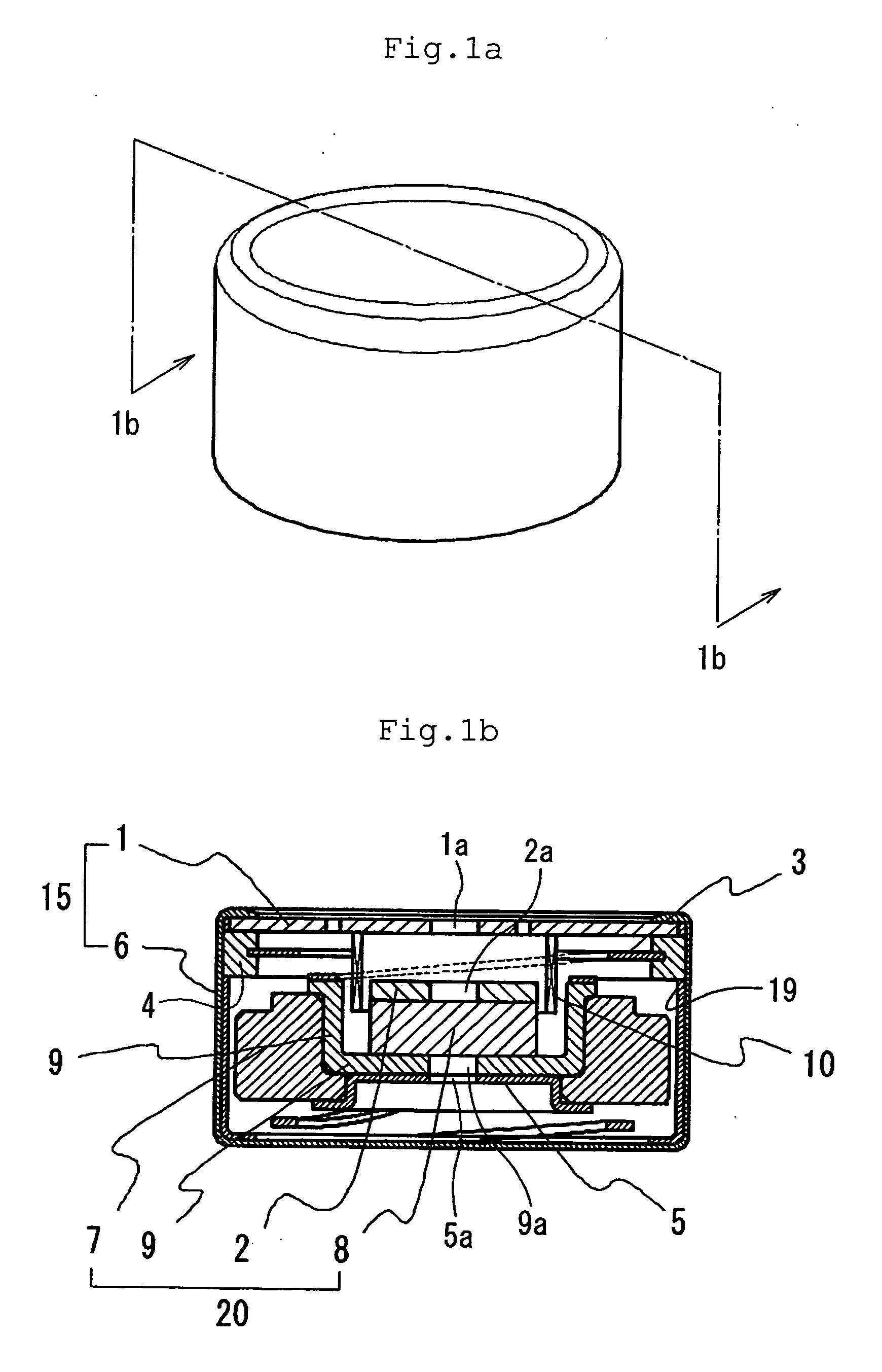
[0035] An embodiment of the vibrator according to the present invention will be explained below with reference to FIGS. 1a to 5.

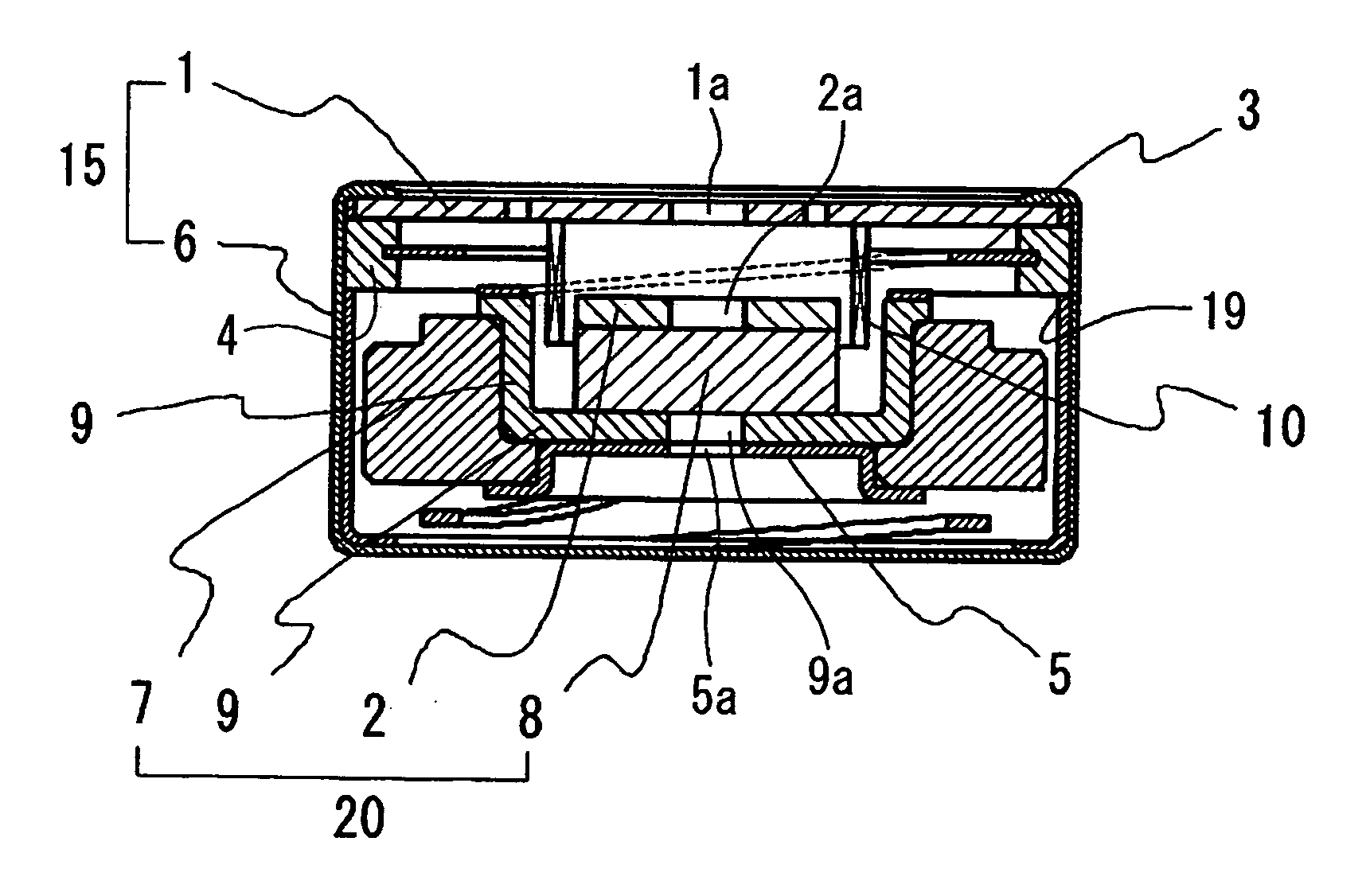
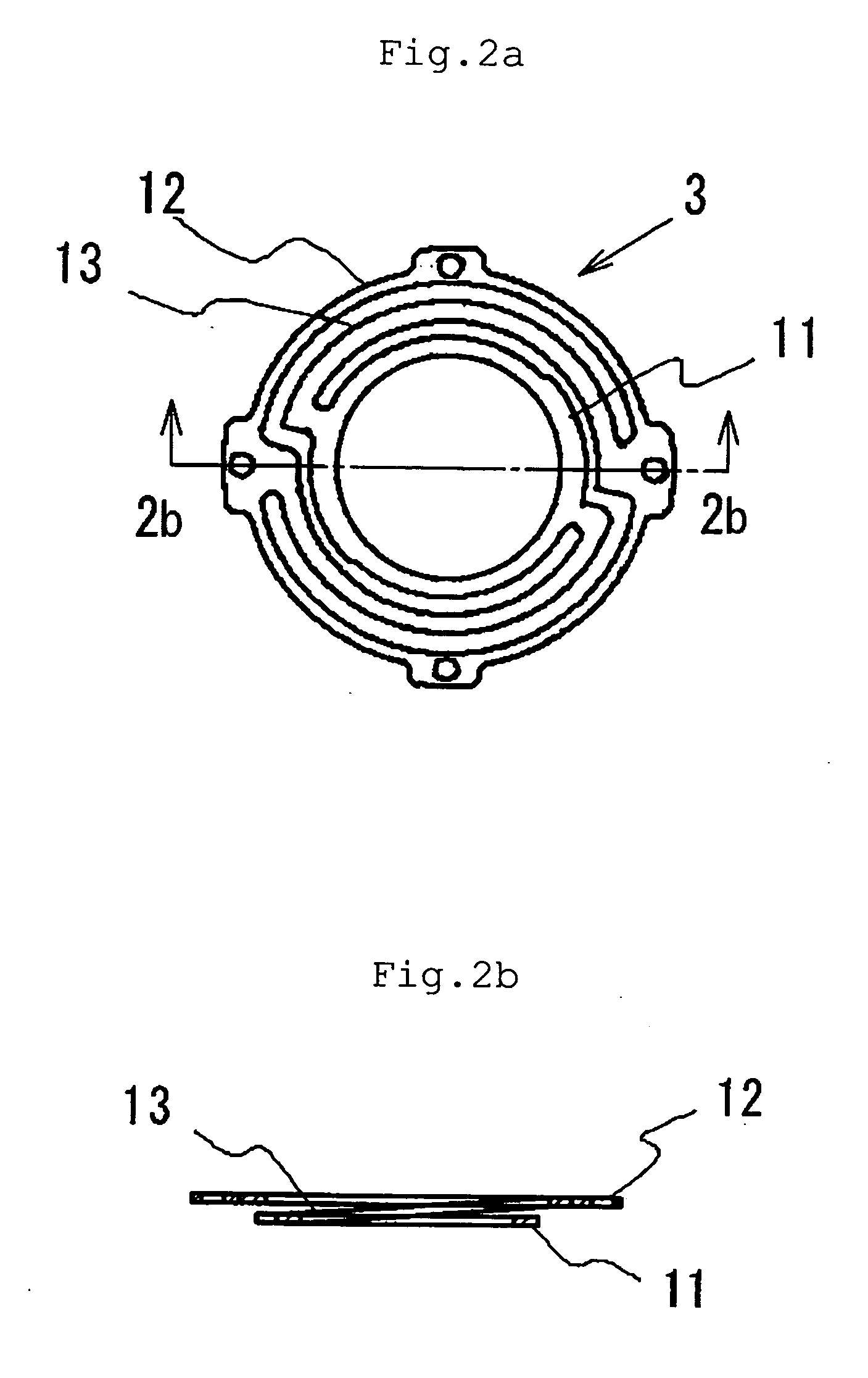
[0036] As shown in FIG. 1b, the vibrator according to the present invention has a cylindrical voice coil 10, a vibrating member 20, and first and second suspensions 3 and 5 that resiliently support the vibrating member 20. When the voice coil 10 is supplied with an alternating current, the vibrating member 20 is reciprocated in the axial direction of the voice coil 10, thereby generating vibrations. The voice coil 10, the vibrating member 20 and the first and second suspensions 3 and 5 are housed in a casing 15. The casing 15 is made of a cup-shaped member 6 that is coaxial with respect to the voice coil 10. The casing 15 further has a circular end plate 1 that supports the voice coil 10 and that closes the opening of the cup-shaped member 6.

[0037] The vibrating member 20 has a cup-shaped yoke 9 placed coaxially with respect to the voice coil 10. The vibr...


PUM


Abstract

A vibrator includes a voice coil and a vibrating member supported by first and second suspensions so as to be vibratory in the axial direction of the coil. Each of the first and second suspensions has an inner ring portion fixed to the vibrating member and an outer ring portion fixed to a casing of the vibrator. The inner and outer ring portions are connected through arcuate portions. Each arcuate portion has a first end connected to the inner ring portion and a second end connected to the outer ring portion. The arcuate portions of the first and second suspensions extend from the first end to the second end, respectively, in the same circumferential direction as seen from one side of the axial direction.

Description

[0001] This application claims priority under 35 U.S.C. §119 to Japanese Patent Application Nos. JP2006-002127 filed Jan. 10, 2006, and JP2006-026447 filed Feb. 3, 2006, the entire content of which is hereby incorporated by reference. BACKGROUND OF THE INVENTION [0002] 1. Field of the Invention [0003] The present invention relates to a vibrator that may be incorporated in a small-sized device such as a cellular phone, a watch and other portable devices. More particularly, the present invention relates to a vibrator used in a cellular phone, e.g. to inform the user of an incoming call. [0004] 2. Description of the Related Art [0005] Conventionally, a portable terminal device such as a cellular phone has a vibrator incorporated therein as a device that informs a user of an incoming call by vibrations of the phone body. Regarding the vibrator, there has been a demand for miniaturization. Under these circumstances, the present applicant proposed a small-sized vibrator as shown in FIG. 8...

Claims


Application Information

Patent Timeline
Patent Type & Authority Applications(United States)
IPC IPC(8): H02K41/00H02K35/00
CPCB06B1/045H04R9/02H02K33/16H04R11/02H04R2400/07H02K7/065H02K7/075
Inventor MIURA, NAOKIWATANABE, TAKAHISA
Owner CITIZEN ELECTRONICS CO LTD
Why Eureka
Try Eureka