
Printing system, printing apparatus, and control method therefor

a printing system and printing technology, applied in the direction of digital output to print units, multi-programming arrangements, instruments, etc., can solve the problems of large installation space for the number of printers and the cluster server, the description language (pdl) widely used as print data is sometimes not suitable for a parallel process, and the inability to meet the needs of a parallel process

Inactive Publication Date: 2007-08-09
CANON KK
View PDF10 Cites 38 Cited by
  • Summary
  • Abstract
  • Description
  • Claims
  • Application Information

AI Technical Summary

Benefits of technology

The present invention provides a technique for distributing the load necessary for a data conversion process and the load necessary for a print process equally to multiple printing apparatuses. This is achieved by generating intermediate data of a plurality of pages based on a print job received from an external apparatus, and transmitting the data to each printing apparatus for execution. The distribution of the number of pages of image data to be printed by each printing apparatus is set based on the data conversion process and the capabilities of each printing apparatus. The invention also includes a method for executing a print process in a printing system with multiple printing apparatuses connected via a network. The technical effects of the invention include improved efficiency and reduced latency in the printing process.

Problems solved by technology

However, a large installation space for the number of printers and the cluster server is necessary.
The page description language (PDL) widely used as print data is sometimes not of a page independent type, and is not suitable for a parallel process.
However, the time taken to convert display list data into image data, i.e., the time taken for RIP changes between pages.

Method used


Image

  • Printing system, printing apparatus, and control method therefor
  • Printing system, printing apparatus, and control method therefor
  • Printing system, printing apparatus, and control method therefor

Examples


second embodiment

[0158]The printing system according to the embodiment (first embodiment) distributes the RIP load by transferring generated display list data of all pages from the master printer to the slave printer. The RIP load is also distributable by transferring display list data of each page. This example will be explained as the second embodiment.

[0159]Details of the second embodiment have been described in the first embodiment, and an outline of the process procedures of the master and slave will be explained with reference to the flowcharts of FIGS. 13 and 14.

[0160]The process procedures of the master printer in the second embodiment will be explained with reference to the flowchart of FIG. 13. A Job Manager module 1520 and Printer Manager module 1526 in FIG. 5 execute a program shown in the flowchart of FIG. 13. As described in the first embodiment, the job ticket designates whether to perform cluster printing, and when cluster printing is to be performed, designates a slave printer. The ...

third embodiment

[0180]The printing system according to the first embodiment distributes the RIP load by transferring generated display list data of all pages from the master printer to the slave printer. The RIP load is also distributable by transferring PDL (Page Description Language) data described in a page independent type PDL. This example will be explained as the third embodiment. The third embodiment will exemplify PDF as typical page independent type PDL data.

[0181]The process procedures of the master printer in the third embodiment will be explained with reference to the flowchart of FIG. 16. A Job Manager module 1520 and Printer Manager module 1526 in FIG. 5 execute a program shown in the flowchart of FIG. 16. The job ticket designates whether to perform cluster printing, and when cluster printing is to be performed, designates a slave printer. The Job Manager module 1520 is notified via a Control API module 1519 of the result of interpretation by a Job Ticket Parser 1531.

[0182]In step S9...

fourth embodiment

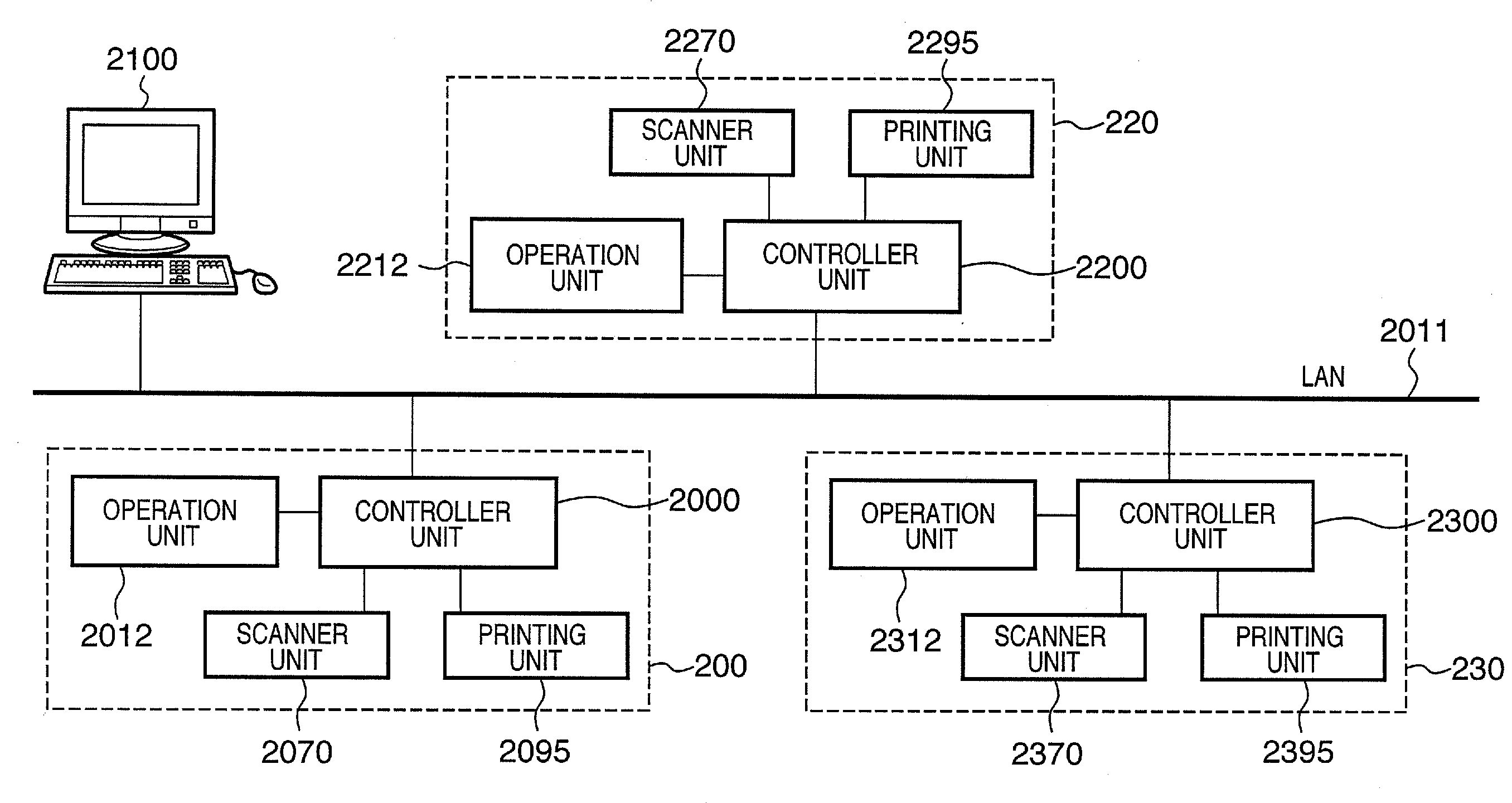
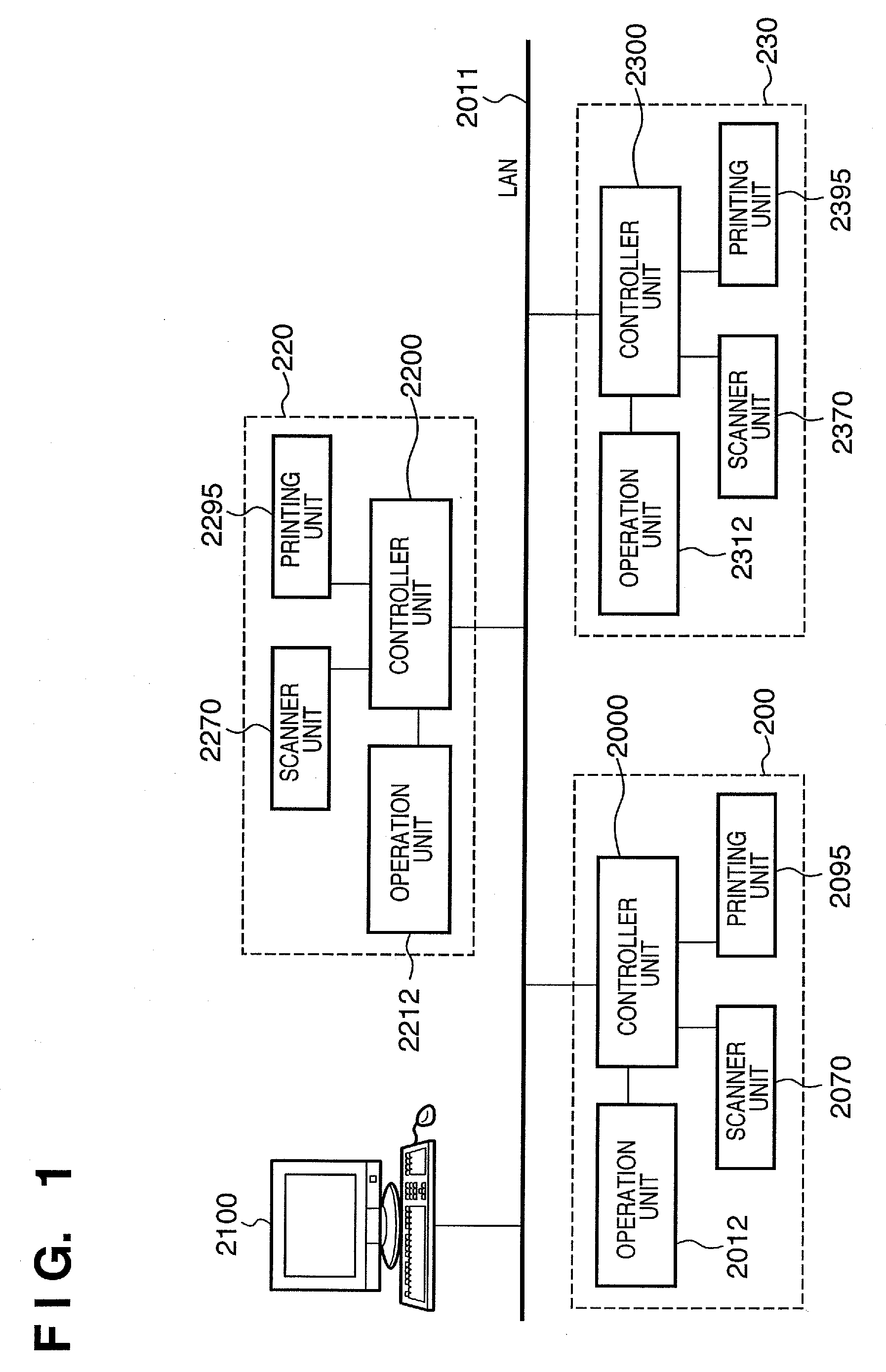
[0201]The first to third embodiments have exemplified cluster printing by two image forming apparatuses, but three or more image forming apparatuses may perform cluster printing. For descriptive convenience, the first embodiment is applied to execute cluster printing by three printers. Assume that the printing units of the three image forming apparatuses have the same print performance (the number of print sheets per unit time).

[0202]A host computer 2100 outputs, to a master image forming apparatus, a job ticket describing the network addresses of image forming apparatuses serving as slave printers A and B. The master-slave relationship is based on an order of the master, slave A, and slave B. That is, slave printer A functions as a slave printer to a master printer, and also functions as a master printer to slave printer B.

[0203]When generating display list data of a print job, the master printer transfers it to slave printers A and B. The operation of each printer upon completion ...


PUM


Abstract

This invention can substantially equally distribute a load necessary for rendering, and can complete printing all pages of one print job at high speed. A master printer interprets received print data, generates display list data as intermediate data for each page, and upon completion of generating intermediate data of all pages, transfers them to a slave printer. The master printer performs rendering (RIP) in an ascending page order of page numbers 1, 2, . . . , whereas the slave printer performs rendering in a descending page order from the final page. When the number of rendered pages held by the master printer does not reach half of all pages upon completion of rendering all pages, the master printer receives the rendering results of deficient pages from the slave printer. Then, each printer prints by almost the same number of pages.

Description

BACKGROUND OF THE INVENTION[0001]1. Field of the Invention[0002]The present invention relates to a technique of printing one print job by distributing it to a plurality of printing apparatuses.[0003]2. Description of the Related Art[0004]There have conventionally been many cluster systems which execute distributed printing using a plurality of printers to advance the print completion timing. This is because the output speed of a printer has an upper limit, and the use of not one expensive high-speed printer but a plurality of low-cost printers sometimes results in low cost.[0005]As for the unit of distribution, there is known a technique of sharing output of copies of a print job requiring printing by a plurality of copies between printers. There is also known a technique of sharing output of pages of a print job requiring one copy between printers.[0006]The cluster system is configured using a dedicated cluster server which performs RIP (Raster Image Process) for print data and dis...

Claims


Application Information

Patent Timeline
Patent Type & Authority Applications(United States)
IPC IPC(8): G06F3/12
CPCG06K15/02G06K15/1856G06K15/1857
Inventor MATSUDA, HIROSHI
Owner CANON KK
Learn More