
System and method for diverting air in a vehicle

Active Publication Date: 2007-08-09
IRVIN MICHAEL
View PDF29 Cites 29 Cited by
  • Summary
  • Abstract
  • Description
  • Claims
  • Application Information

AI Technical Summary

Benefits of technology

[0009] It is another object of this invention to provide a system that uses a vehicle's existing compressed air system for the pressure source in conjunction with relatively simple add-on components that do not require extensive retrofitting.

Problems solved by technology

The accumulation of dirt, precipitation, and / or any other substance on the reflective surface of a motor vehicle's external driving mirror is a common problem for operators of motor vehicles.
This accumulation prevents and obstructs the operator's visibility to the rear and side of the vehicle.
For example, such accumulation could inhibit the operator's ability to see any traffic approaching in an adjoining lane or any vehicles or other obstructions as the vehicle is traveling in reverse.
This condition has the ability to distort the reflective properties of the mirror and can be dangerous for a driver.
This situation is further compounded during periods of darkness when the reflection of headlights upon the moisture covered rearview mirror creates additional visual distortion to images reflected by the mirror.
The situation is most dangerous when the external driving mirrors are the only mirrors on the vehicle that provide the operator with visibility to the rear of the vehicle.
These devices may have some use during a high speed movement of a vehicle; however, at low speeds or when the vehicle is not moving, these devices do not provide adequate air flow to clear the mirrors.
Also, they are inherently incapable of conditioning the air flow such as to increase its temperature or reduce humidity, all of which may be helpful in extreme weather conditions.
However, many of these systems are overly complex and hence vehicle-specific.
They assume incorporation of unique design elements with the on-board air-system of the vehicle and are not easily adapted to be used for a variety of different vehicles.
In addition, in many cases the air blowers are underpowered and blow the air at an acute angle towards the surface of the mirror so that the incoming moist and cold air flow simply overwhelms their function.

Method used


Image

  • System and method for diverting air in a vehicle
  • System and method for diverting air in a vehicle
  • System and method for diverting air in a vehicle

Examples


Embodiment Construction

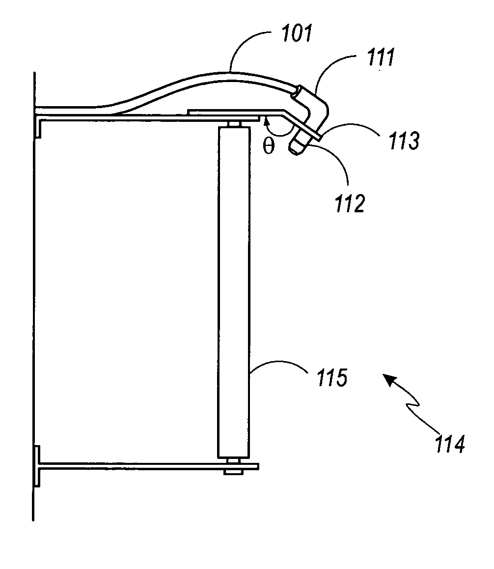
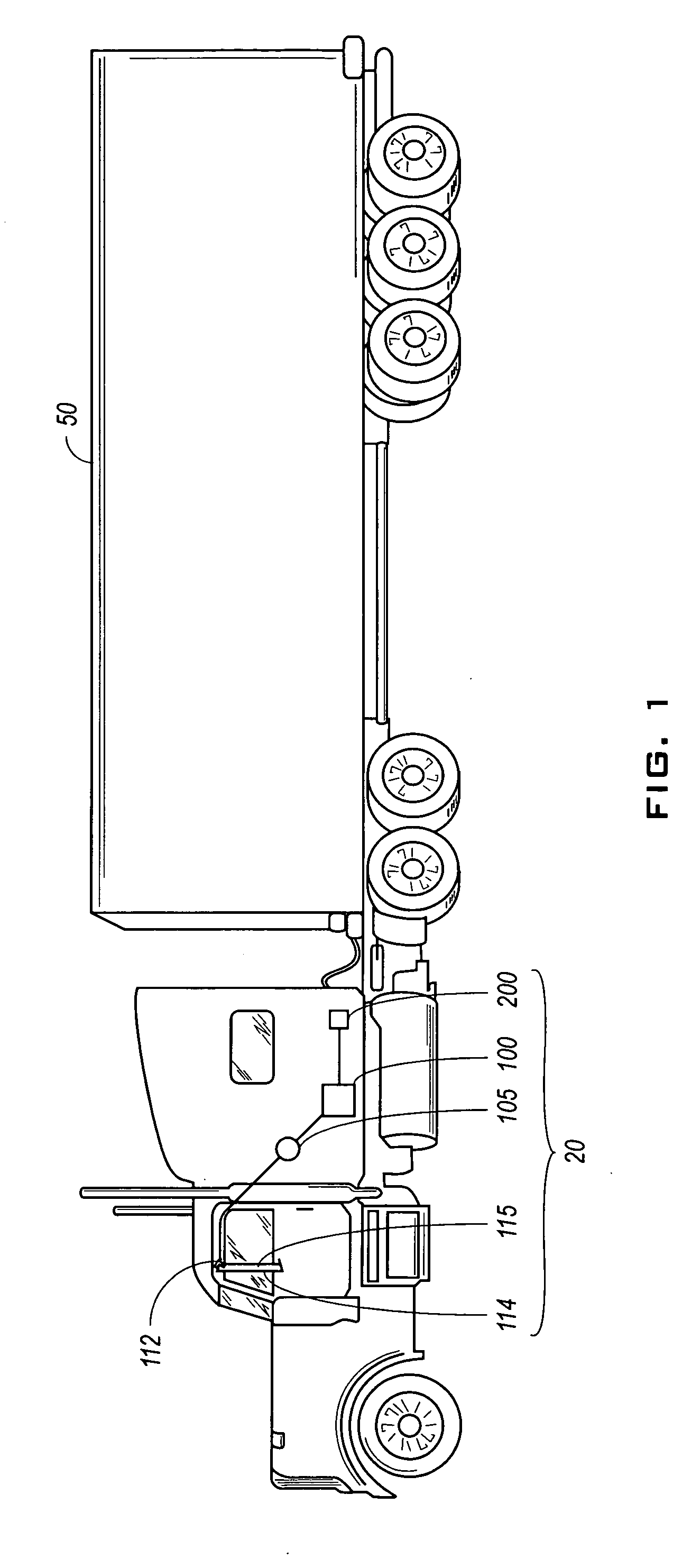
[0018] Embodiments of the invention relate to a mirror clearing system configured to remove dirt, precipitation, and / or any other substance from a vehicular mirror. Although the present invention can be used in any vehicle having an air compressor or other sufficient source of compressed air, in one embodiment it is used in commercial transport trucks (i.e. trucks having more than two axles), for example tractor-trailers. These larger vehicles typically utilize pressurized air braking systems, which can be configured as part of the mirror clearing system.

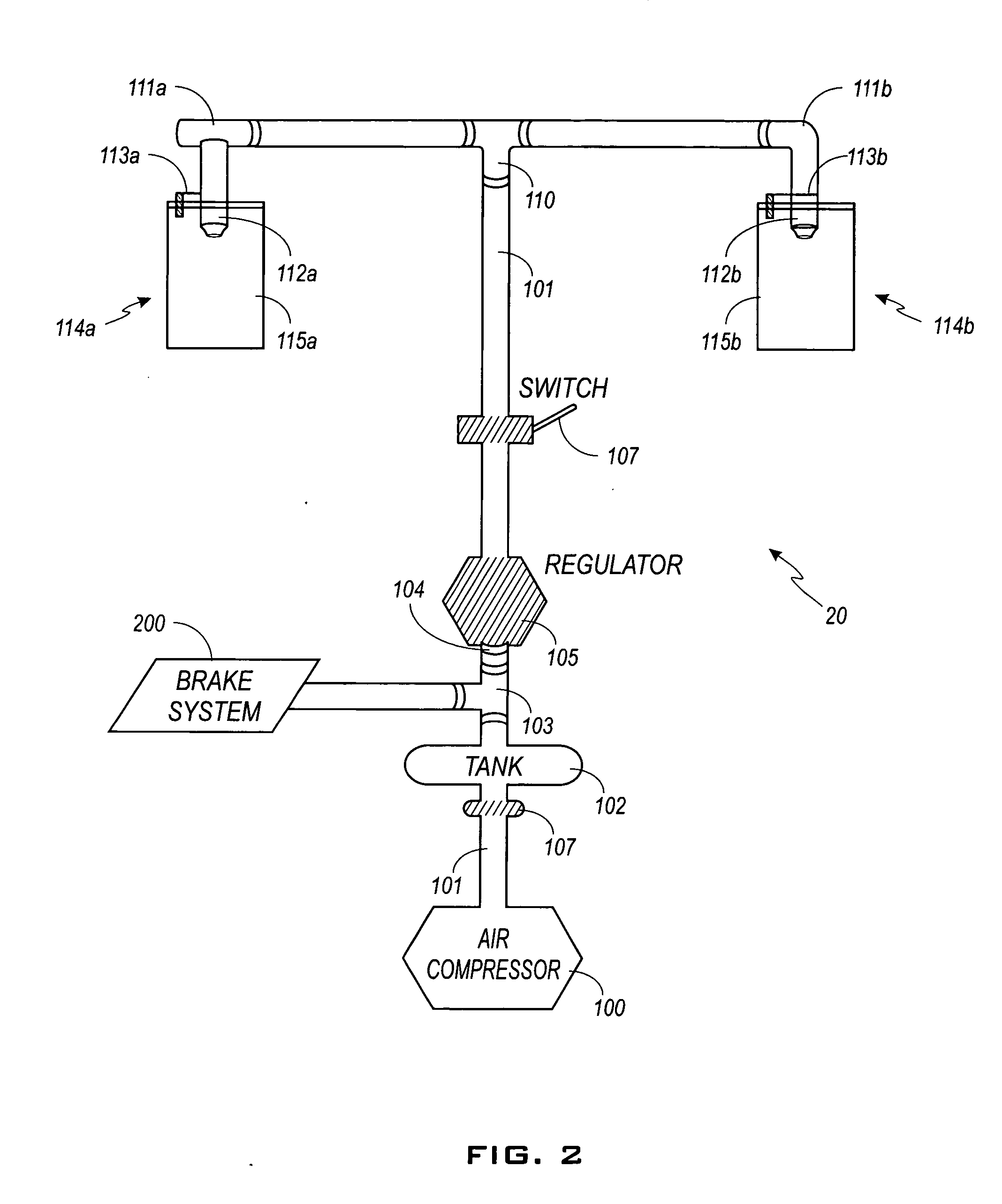
[0019] Many vehicles, typically heavy-duty or larger vehicles, use air brake systems. Air brake systems use high pressure air—typically about 100 pounds per square inch (psi)—to apply the brakes. Air is generally supplied by an engine driven air compressor and stored in tanks on the tractor and trailer. When the brakes are applied the air usually comes from the compressed air tanks, which are subsequently recharged by the compresso...


PUM


Abstract

The present invention comprises a system and method for clearing an external driving mirror on a vehicle. The system and method comprise providing a stream of compressed air to clear water, dirt, and / or other substances from the reflective surface of an external driving mirror. This system uses the air source of the vehicle in conjunction with a safety pressure protection valve. This pressure protection valve will shut down the mirror clearing system in the event that the vehicle's primary air system cannot provide a certain minimum amount of air pressure.

Description

BACKGROUND OF THE INVENTION [0001] 1. Field of the Invention [0002] This invention relates to a system for clearing the reflective surface of an external driving mirror of a vehicle. More particularly, the invention relates to a system and method for blowing compressed air onto side mirrors of a truck in order to clear debris and rain from the mirrors. [0003] 2. Description of the Related Art [0004] The accumulation of dirt, precipitation, and / or any other substance on the reflective surface of a motor vehicle's external driving mirror is a common problem for operators of motor vehicles. This accumulation prevents and obstructs the operator's visibility to the rear and side of the vehicle. For example, such accumulation could inhibit the operator's ability to see any traffic approaching in an adjoining lane or any vehicles or other obstructions as the vehicle is traveling in reverse. Moisture will collect on the viewing surface of exterior rearview mirrors in heavy fog or rain. This...

Claims


Application Information

Patent Timeline
IPC IPC(8): B60R1/06
CPCB60S1/54B60R1/0602
Inventor IRVIN, MICHAEL
Owner IRVIN MICHAEL
Features
  • Generate Ideas
  • Intellectual Property
  • Life Sciences
  • Materials
  • Tech Scout
  • Unparalleled Data Quality
  • Higher Quality Content
  • 60% Fewer Hallucinations
Learn More