Automatic clamp changing apparatus

a technology of automatic clamping and changing apparatus, which is applied in the direction of manufacturing tools, couplings, transportation and packaging, etc., can solve the problems of low productivity, waste of valuable time and power, and inability to continuously operate the machine during the production cycl

Inactive Publication Date: 2007-08-16
HONG FU JIN PRECISION IND (SHENZHEN) CO LTD +1
View PDF8 Cites 2 Cited by
  • Summary
  • Abstract
  • Description
  • Claims
  • Application Information

AI Technical Summary

Benefits of technology

[0004]In an exemplary embodiment, a clamp changing apparatus includes a holder including a plurality of clamp-holding devices, each of which holds a clamp thereon, a robot including a shaft, and a coupling device secured on the shaft o

Problems solved by technology

Detachment of the clamp and replacement with another clamp is done while the machine is stopped, and thus operation of the machine cannot be continuous during production cycles.
Consequently, val

Method used


Image

  • Automatic clamp changing apparatus
  • Automatic clamp changing apparatus
  • Automatic clamp changing apparatus

Examples


Embodiment Construction

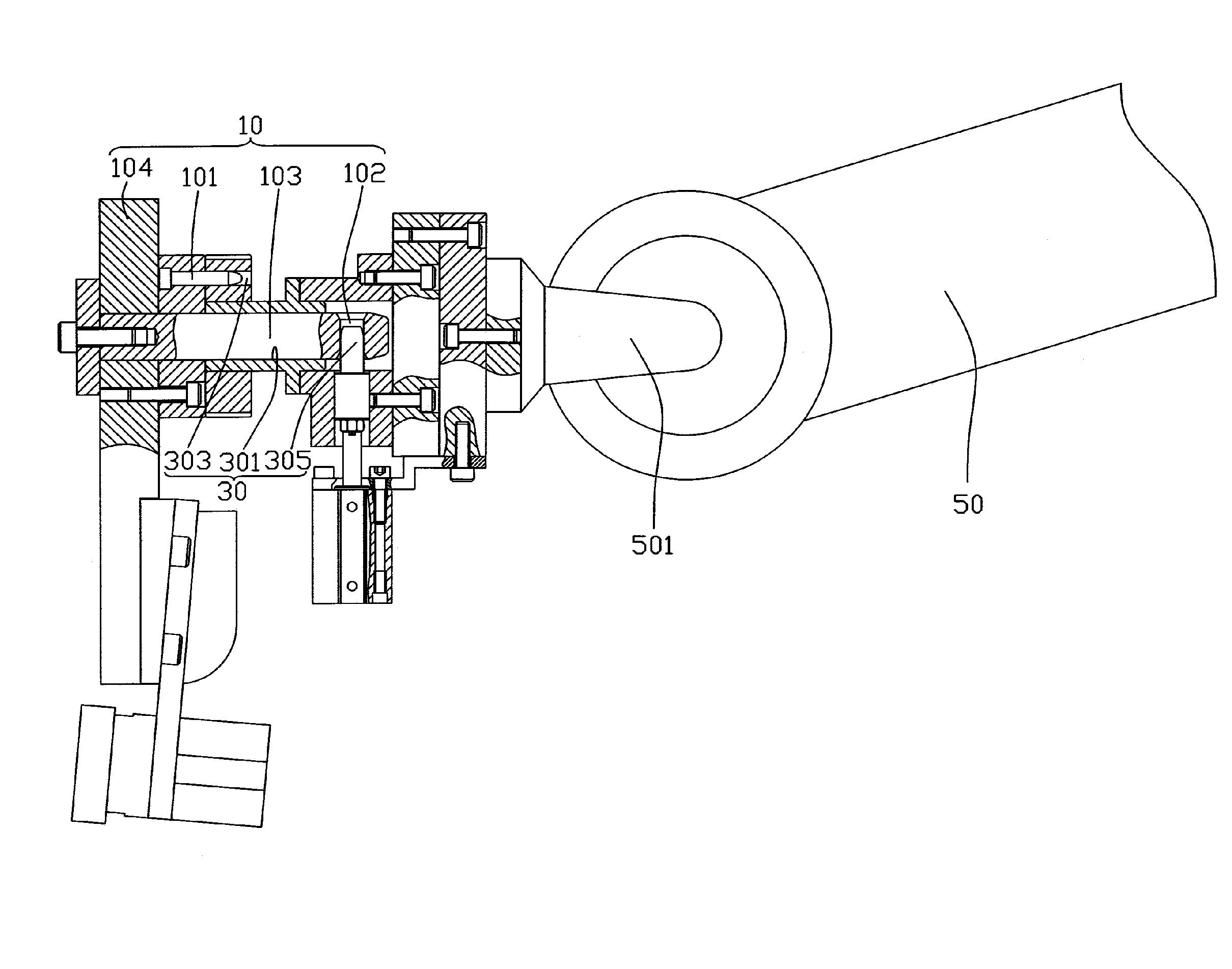
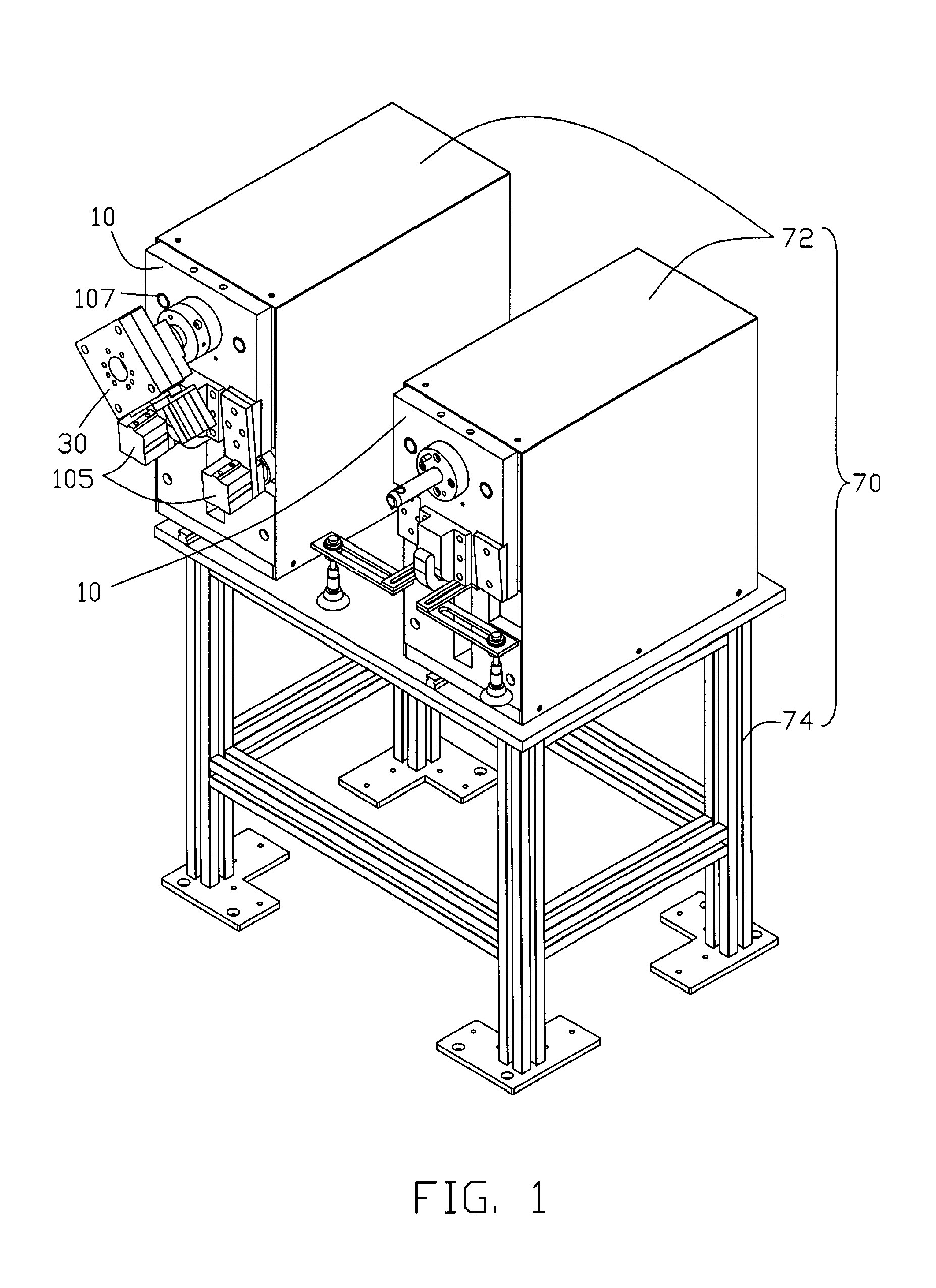
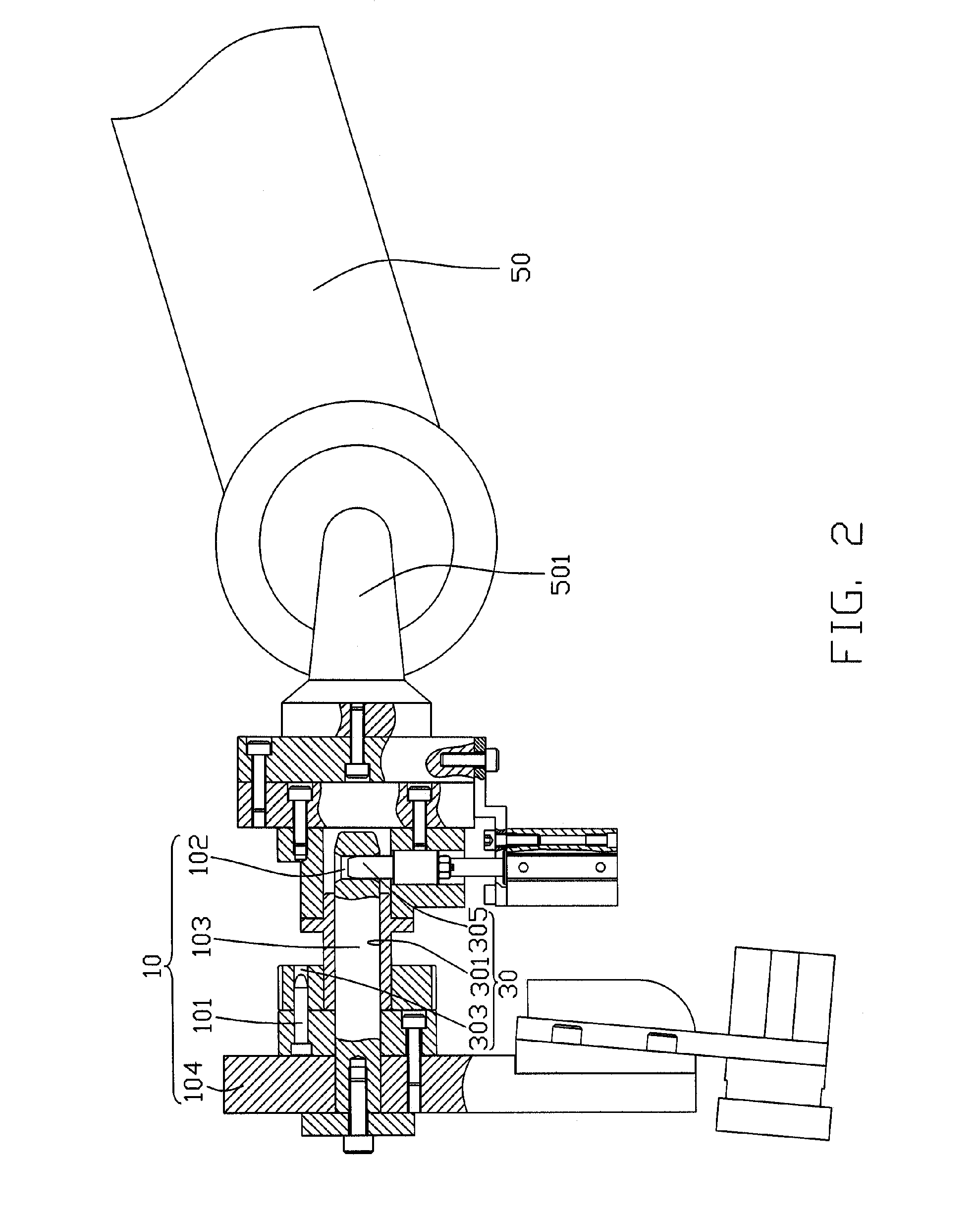
[0012]Referring to FIGS. 1 and 2, a clamp changing apparatus of an exemplary embodiment of the present invention comprises a holder 70, a robot 50, and a coupling device 30. The holder 70 comprises a plurality of clamp-holding devices 72, each of which holds a clamp 10 thereon. The robot 50 comprises an output shaft 501. The coupling device 30 is mounted to the output shaft 501. The output shaft 501 is used for controlling the movement of the clamp 10 mounted to the coupling device 30.

[0013]Referring also to FIG. 3, the clamp 10 of the exemplary embodiment of the present invention is shown. The clamp 10 comprises a clamp body 104 having a first surface 108 and an opposite second surface 109, and the first surface 108 having a primary shaft 103 perpendicularly disposed thereon. The primary shaft 103 defines a fixing hole 102 extending therethrough in a radial direction at a distal end thereof. The clamp 10 further comprises a positioning pin 101 perpendicularly disposed on the first ...


PUM


Abstract

A clamp changing apparatus includes a holder (70) including a plurality of clamp-holding devices (72), each of which holding a clamp (10) thereon, a robot (50) including a shaft (501), and a coupling device (30) secured on the shaft of the robot. The robot selects one of the clamps held on the clamp-holding devices according to a predetermined machining program therein, changes out a used clamp for the selected clamp, and mounts the selected clamp on the coupling device.

Description

FIELD OF THE INVENTION[0001]The present invention pertains to a clamp changing apparatus, and particularly to an automatic clamp changing apparatus capable of automatically changing a currently-used clamp for a next clamp to be used during operation if necessary.DESCRIPTION OF RELATED ART[0002]Until now, the operation of changing a clamp of a robot or a machine, in particular a complicated or heavy clamp, has had to be carried out manually by at least one operator using tools such as levers and screw drivers or other special tools. Detachment of the clamp and replacement with another clamp is done while the machine is stopped, and thus operation of the machine cannot be continuous during production cycles. Consequently, valuable time and power are wasted, thereby leading to low productivity.[0003]Therefore, a heretofore unaddressed need exists in the industry to overcome the aforementioned deficiencies and inadequacies.SUMMARY OF THE INVENTION[0004]In an exemplary embodiment, a clam...

Claims


Application Information

Patent Timeline
IPC IPC(8): F16D1/08
CPCB23Q3/103B25J15/04Y10T403/22Y10S483/901Y10T483/1809Y10T403/593Y10T483/17
Inventor OU, CHUN-NANXING, JIAN-LONGBAO, RONG-MOUSU, CHENG-BINYUAN, XIAO-YUNWANG, JIN
Owner HONG FU JIN PRECISION IND (SHENZHEN) CO LTD
Why Eureka
Try Eureka