Airbag device for vehicle

a technology for airbags and vehicles, applied in the direction of vehicle components, pedestrian/occupant safety arrangements, vehicular safety arrangments, etc., can solve the problems of complicated airbag structure, reduce the reaction force applied to the occupant's head, and reduce the reaction force. , the structure of the airbag body is simpl

Inactive Publication Date: 2007-08-16
TOYOTA JIDOSHA KK
View PDF6 Cites 20 Cited by
  • Summary
  • Abstract
  • Description
  • Claims
  • Application Information

AI Technical Summary

Benefits of technology

[0010]That is, according to the above-described aspect, the airbag body securely restrains the shoulders of the occupant, and the low-pressure portion softly receives the occupant's head to reduce the reaction force applied to the occupant's head and neck.
[0011]Further, in the above-described aspect, the airbag body has a single-chamber structure, and the low-pressure portion is provided in the area of the airbag body that faces the occupant when the airbag body is inflated and deployed. Therefore, a conventional airbag may be used for the airbag body. Thus, unlike the art described in the above-described Japanese Patent Application Publication No. JP-A-2001-233157, the shape of the cut bag foundation fabric does not need to be changed. Accordingly, there is no need change the process of sewing the airbag body, and the process of combining a plurality of bags is not necessary. Thus, the structure of the airbag body is very simple.
[0012]As described above, the airbag device for a vehicle according to the first aspect of the invention reduces the reaction force applied to the occupant's head and neck while restraining the shoulders of the occupant. Further, the structure of the airbag body is simplified.

Problems solved by technology

Thus, the structure of the airbag is complicated.

Method used


Image

  • Airbag device for vehicle
  • Airbag device for vehicle
  • Airbag device for vehicle

Examples


first embodiment

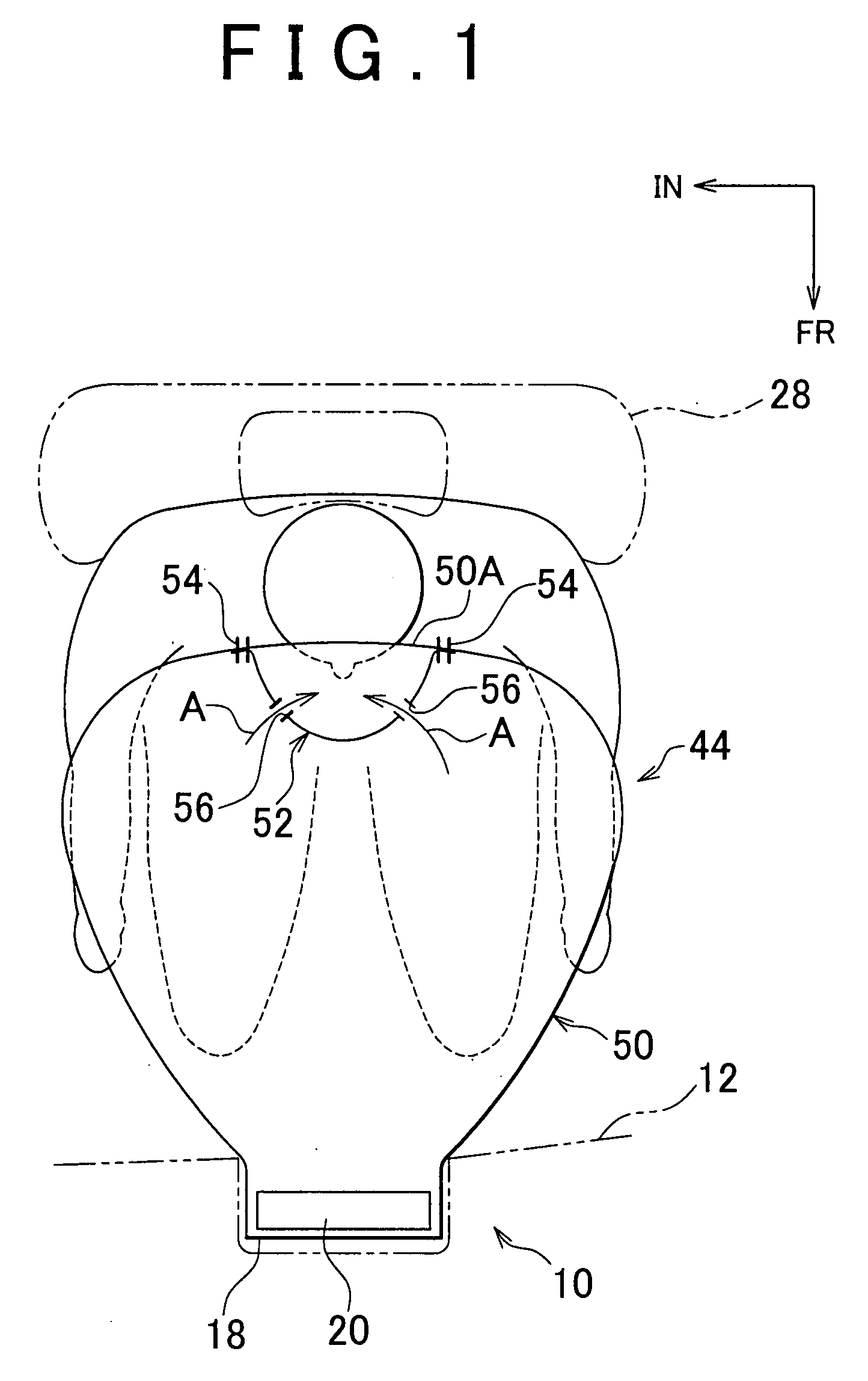
[0019]Hereinafter, an airbag device for a vehicle according to the invention will be described with reference to FIG. 1 to FIG. 4. In the drawings, arrow FR points to the front of the vehicle, arrow UP points up with respect to the vehicle, and arrow IN points to the inside of the vehicle in the vehicle width direction.

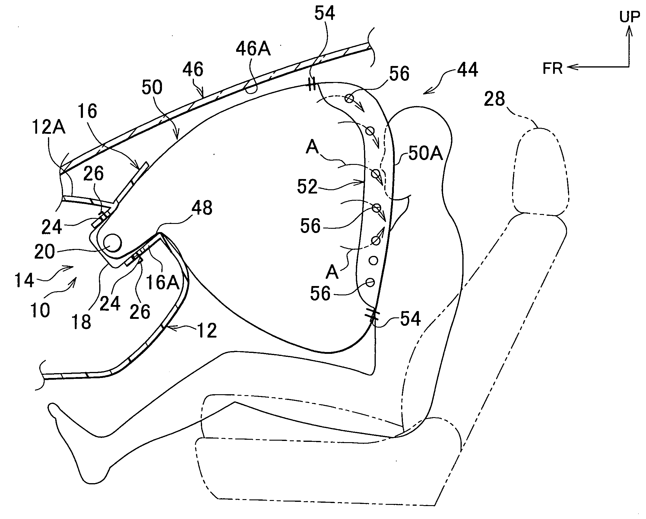
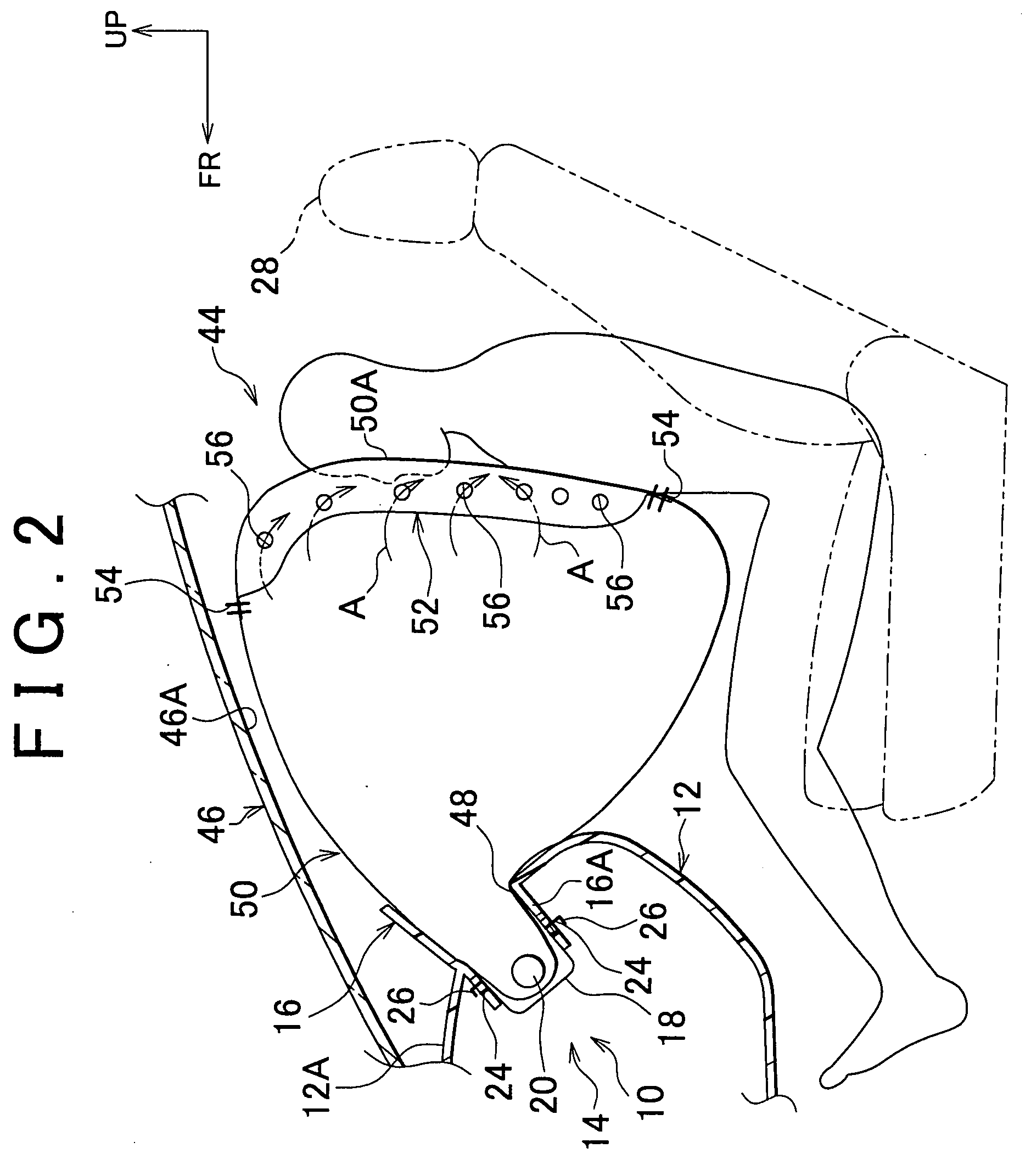
[0020]FIG. 1 shows the plan cross-sectional structure of a deployed passenger-side airbag device 10, which is regarded as the airbag device for a vehicle according to the embodiment. FIG. 2 shows the vertical sectional structure of the deployed passenger-side airbag device 10. FIG. 3 is a perspective view showing the main part of the passenger-side airbag device 10 according to the embodiment.

[0021]As shown in FIG. 1 to FIG. 3, the passenger-side airbag device 10 is arranged on the passenger side of the upper surface 12A of an instrument panel 12. This passenger-side airbag device 10 mainly includes an airbag module 14 housing functioning components, and an airbag doo...

second embodiment

[0040]As shown in FIG. 5, in the passenger-side airbag device 10 only both side portions in the peripheral portion of the low-pressure portion 70 are sewn to, or adhere to the airbag body 50, instead of sewing the entire peripheral portion of the low-pressure portion 70 to the airbag body 50. A gas inlet 72 is formed at each of the upper end and lower end of the low-pressure portion 70. The gas flows into the low-pressure portion 70 through the gas inlets 72. The gas inlet 72 is regarded as the communication portion.

[0041]The gas inlet 72 formed at each of the upper end and lower end of the low-pressure portion 70 is narrower than a general portion 70A.

[0042]With the above-described configuration, when a frontal collision occurs, after the gas inflates the airbag body 50, the gas flows into the low-pressure portion 70 through the gas inlets 72 to inflate the low-pressure portion 70 (as shown by the arrow B in FIG. 5). Accordingly, by changing the width of the gas inlets 72, the pre...


PUM


Abstract

An airbag device for a vehicle includes a gas supply portion, an airbag body, and a low pressure portion. When a vehicle collision occurs, the gas supply portion injects gas into an airbag body. The airbag body has a single-chamber structure. When the airbag body receives the gas from the gas supply portion, the airbag body is inflated and deployed toward an occupant to restrain the shoulders of the occupant. The low-pressure portion is provided in the same area of the airbag body, which faces the occupant when the airbag body is inflated and deployed, to protect the occupant's head. When the airbag body is inflated and deployed, the low-pressure portion is inflated such that the pressure in the low-pressure portion is lower than the pressure in the airbag body.

Description

INCORPORATION BY REFERENCE[0001]The disclosure of Japanese Patent Application No. 2006-039289 filed on Feb. 16, 2006 including the specification, drawings and abstract is incorporated herein by reference in its entirety.BACKGROUND OF THE INVENTION[0002]1. Field of the Invention[0003]The invention relates to an airbag device for a vehicle, which includes an airbag that is deployed toward an occupant when a collision occurs.[0004]2. Description of the Related Art[0005]Japanese Patent Application Publication No. JP-A-2001-233157 describes a passenger-side airbag device, in which a recess is formed beforehand in the area of an airbag that contacts the occupant's head when the airbag is deployed. Thus, the reaction force applied to the occupant's head is reduced.[0006]However, in the above-described passenger-side airbag device, for example, the shape of bag foundation fabric (the shape of the cut bag foundation fabric) needs to be changed, or the airbag needs to be divided into a plural...

Claims


Application Information

Patent Timeline
Patent Type & Authority Applications(United States)
IPC IPC(8): B60R21/237B60R21/239B60R21/231B60R21/00B60R21/01B60R21/16
CPCB60R21/233B60R21/239B60R2021/23324B60R2021/0048B60R2021/0004
Inventor SEKIZUKA, MAKOTO
Owner TOYOTA JIDOSHA KK
Why Eureka
Try Eureka