Electrical filter

Active Publication Date: 2007-08-16
INFINEON TECH AG
View PDF4 Cites 12 Cited by
  • Summary
  • Abstract
  • Description
  • Claims
  • Application Information

AI Technical Summary

Benefits of technology

[0019] In accordance with a first aspect, an electrical filter has at least four terminals, two inductances and two capacitors. The first inductance is connected between the first terminal and the second terminal, and a second inductance is connected between the third terminal and the fourth terminal. The first capacitance is connected between the first terminal and a reference potential, and the

Problems solved by technology

In systems using differential data lines for transmitting signals, a considerable problem is filtering out external disturbances in the broadest band possible.
According to the conventional art, such signals are realized by discrete, comparatively large and expensive transformers using ferrites to increase inductance.
Even if today's solutions exhibit a relatively low direct current resistance, however, the disadvantages of these solutions exceed this advantage by far.
The disadvantages of this solution in particular are that the difference in attenuation for the common mode and the differential mode is relatively low and that the attenuation of the differential mode is reduced considerably with higher frequencies, i.e. for example in a frequency range above 1 GHz, which becomes evident from measurements of the typical attenuation as a function of the frequency in the common mode and the differential mode.
Additionally, the frequency range of the differential signal usable is limited by the self-resonance of the transformer and / or the ferrite material used.
As another disadvantage, frequently additional costs are caused due to the fact that measures must be taken for a separate ESD (electrostatic discharge) protection against electrostatic discharges since these filters frequently are located at the interfaces of PCs or other apparatuses from the field of consumer electronics and telecommunications.
Even realizing a multi-stage filter concept of the conventional art is of particular disadvantage since in this case several, comparatively large devices have to be connected in series.
Frequently, especially in the field of mobile applications, there is no space available for this.
It is possible by this increase in the values L1 and L2 of the inductances 810 and 820 to, for example, achieve an attenuation of around 29 dB at around 1 GHz, however, this requires a considerable increase in the inductances L1 and L2 of the two inductances 810, 820 of the transformer of the filter shown in FIG. 5a. Such an increase generally also causes a considerable increase in the space required which frequently, in particular in mobile applications, is not available.

Method used


Image

  • Electrical filter
  • Electrical filter
  • Electrical filter

Examples


first embodiment

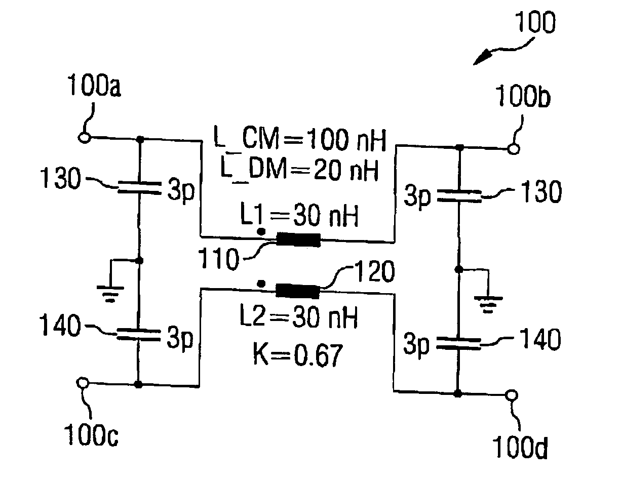
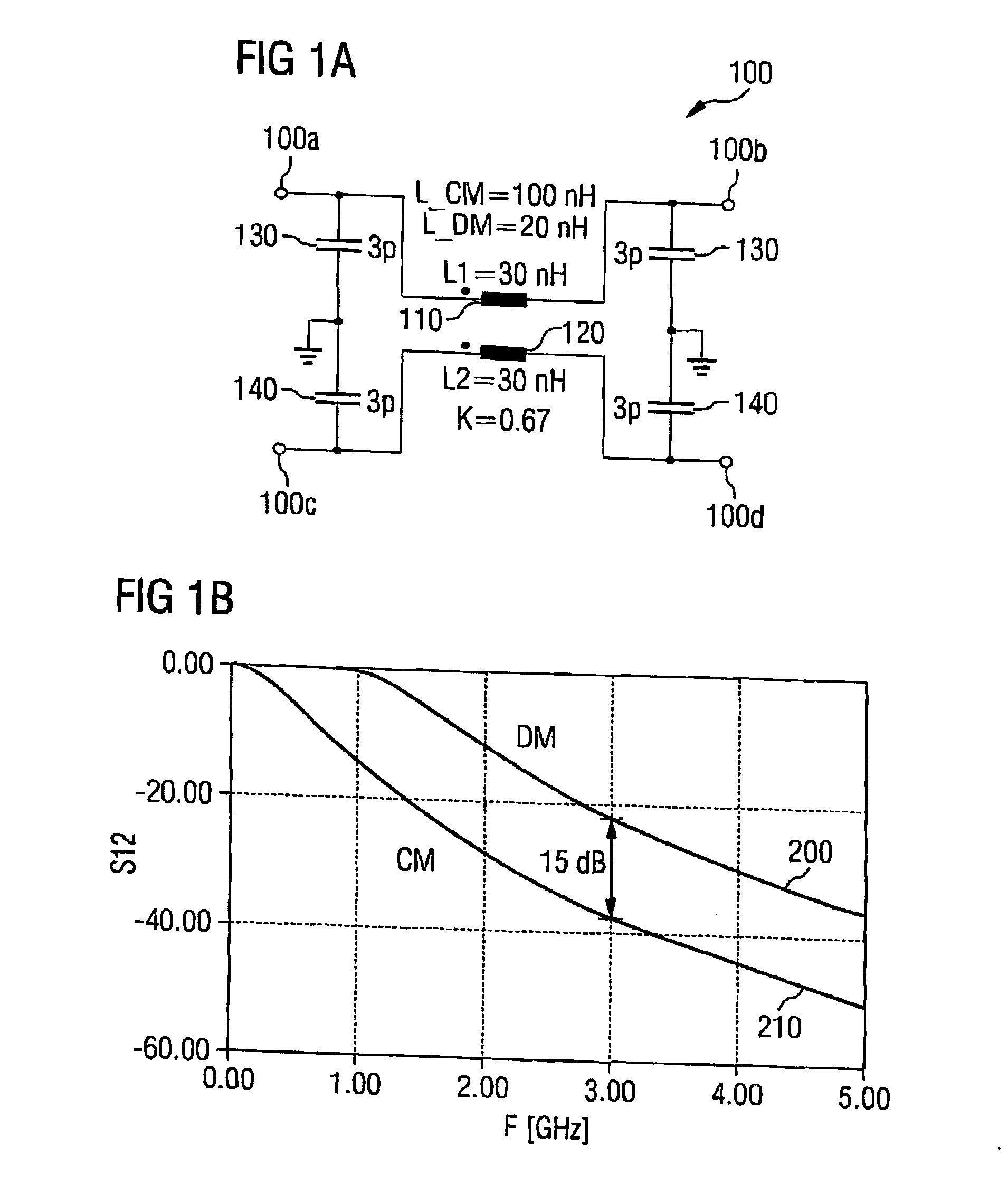
[0026] an inventive electrical filter will be described below referring to FIGS. 1 to 4.

[0027] In general, the exemplary embodiments described herein at least partly based on the finding that an electrical filter having an improved filter characteristic for differential signals and common mode signals can be achieved by using an LC filter using a transformer having a coupling coefficient of a magnitude smaller than 1.

[0028] At least some embodiments of the invention include an electrical filter that is an LC low-pass filter, i.e. a filter comprising both an inductance and a capacitance. Such a filter differs clearly from the L filter known from the conventional art comprising an inductance but no capacitance. The inductive portion of such an embodiment of the inventive electrical filter is, as is the case in the conventional art, formed by a coupled coil pair and / or a coupled pair of two inductances forming a transformer having high inductance values. The two inductances of the tra...

second embodiment

[0052]FIG. 3a shows such an inventive electrical filter 300 which in principle is a series connection of two filter stages 100-1, 100-2 of the inventive filter 100 shown in FIG. 1a. The setup and dimensioning of the two filter stages 100-1 and 100-2 only differ from the setup and dimensioning of the inventive filter 100 shown in FIG. 1a in that the filter 300 principally has a parallel connection of two capacitances 130 and 140 each at the “interface” of the two filters stages 100-1 and 100-2, so that the filter 300, instead of a parallel connection of two capacitances 130 and / or 140, each has a capacitance 130′ and / or 140′ the capacitance values of which are doubled compared to the capacitances 130, 140, i.e. they both have a capacitance of 6 pF each. In this case, too, in analogy to the filter 100, the two filter stages 100-1 and 100-2 have an effective inductance L_DM=20 nH in the differential mode and an effective inductance L_CM=100 nH in the common mode.

[0053]FIG. 3b shows two...

third embodiment

[0055]FIG. 4 shows an inventive filter 500 which is a series connection of three filter stages 100-1, 100-2, 100-3 of the inventive filter 100, i.e. a three-stage filter. Here, too, the dimensioning of the individual filter stages 100-1, 100-2, 100-3 principally does not deviate from the dimensioning of the filter 100 shown in FIG. 1a, wherein, however, at the two “interfaces” of the filter stages 100-1 and 100-2 and / or the filter stages 100-2 and 100-3, due to the resulting parallel connection of two capacitances 130 and / or 140 each, capacitances 130′ and 140′ having a capacitance doubled relative to the capacitances 130 and 140, respectively, are implemented in the filter 500 at these positions. Apart from this, the individual filter stages 100-1, 100-2, 100-3 do not differ from the inventive filter 100 shown in FIG. 1a, so that each filter stage 100-1, 100-2, 100-3 in the common mode has an effective inductance L_CM=100 nH and an effective inductance L_DM=20 nH in the differentia...


PUM


Abstract

An electrical filter has at least four terminals, two inductances and two capacitors. The first inductance is connected between the first terminal and the second terminal, and a second inductance is connected between the third terminal and the fourth terminal. The first capacitance is connected between the first terminal and a reference potential, and the second capacitance is connected between the third terminal and the reference potential. The first inductance and the second inductance form a transformer having a coupling coefficient of a magnitude such that the filter acts as a low-pass filter for differential signals and common mode signals, a cutoff frequency for differential signals being higher than a cutoff frequency for common mode signals.

Description

CROSS-REFERENCE TO RELATED APPLICATION [0001] This application claims priority from German Patent Application No. 10 2006 003 379.5, which was filed on Jan. 24, 2006, and is incorporated herein by reference in its entirety. BACKGROUND OF THE INVENTION [0002] 1. Field of the Invention [0003] The present invention relates to an electrical filter, in particular to an electrical filter which can be used for filtering external disturbances in differential data lines. [0004] 2. Description of Related Art [0005] In systems using differential data lines for transmitting signals, a considerable problem is filtering out external disturbances in the broadest band possible. Examples of this are disturbances which are, for example, caused by the fact that strong transmitters couple in the data lines so that these disturbances generally occur as common mode signals. Common mode signal in this context means a signal which is present on at least two signal or data lines in a common mode. Signals wh...

Claims


Application Information

Patent Timeline
IPC IPC(8): H03H7/01
CPCH03H7/09H03H1/0007
Inventor KEBINGER, HERBERTKLEIN, WOLFGANG
Owner INFINEON TECH AG
Why Eureka
Try Eureka