
Imaging apparatus, and method and program for controlling an imaging apparatus

a technology of imaging apparatus and control method, which is applied in the direction of exposure control, camera filters, instruments, etc., can solve the problems of difficulty in properly setting, two threshold values or the difference between, and can become improper depending on the environment or the subject, and achieve high reliability in taking an imag

Inactive Publication Date: 2007-08-16
SONY CORP
View PDF1 Cites 6 Cited by
  • Summary
  • Abstract
  • Description
  • Claims
  • Application Information

AI Technical Summary

Benefits of technology

The patent text describes an imaging apparatus that can control the operation of an infrared cutoff filter to ensure that it is properly inserted into the incident light path to an image sensing device, regardless of the environment of illumination. This technique allows for reliable image capture in various lighting conditions. The imaging apparatus includes a first detecting means to determine if there is a difference between the current illuminance of a subject and a reference value of the illuminance, and a filter control means to insert or extract the infrared cutoff filter based on the difference. The technique ensures that the infrared cutoff filter is inserted when the difference is equal to or greater than a predetermined threshold value, and remains inserted for a predetermined period of time. This technique improves the reliability of the imaging apparatus and ensures that the image is captured in a highly reliable fashion.

Problems solved by technology

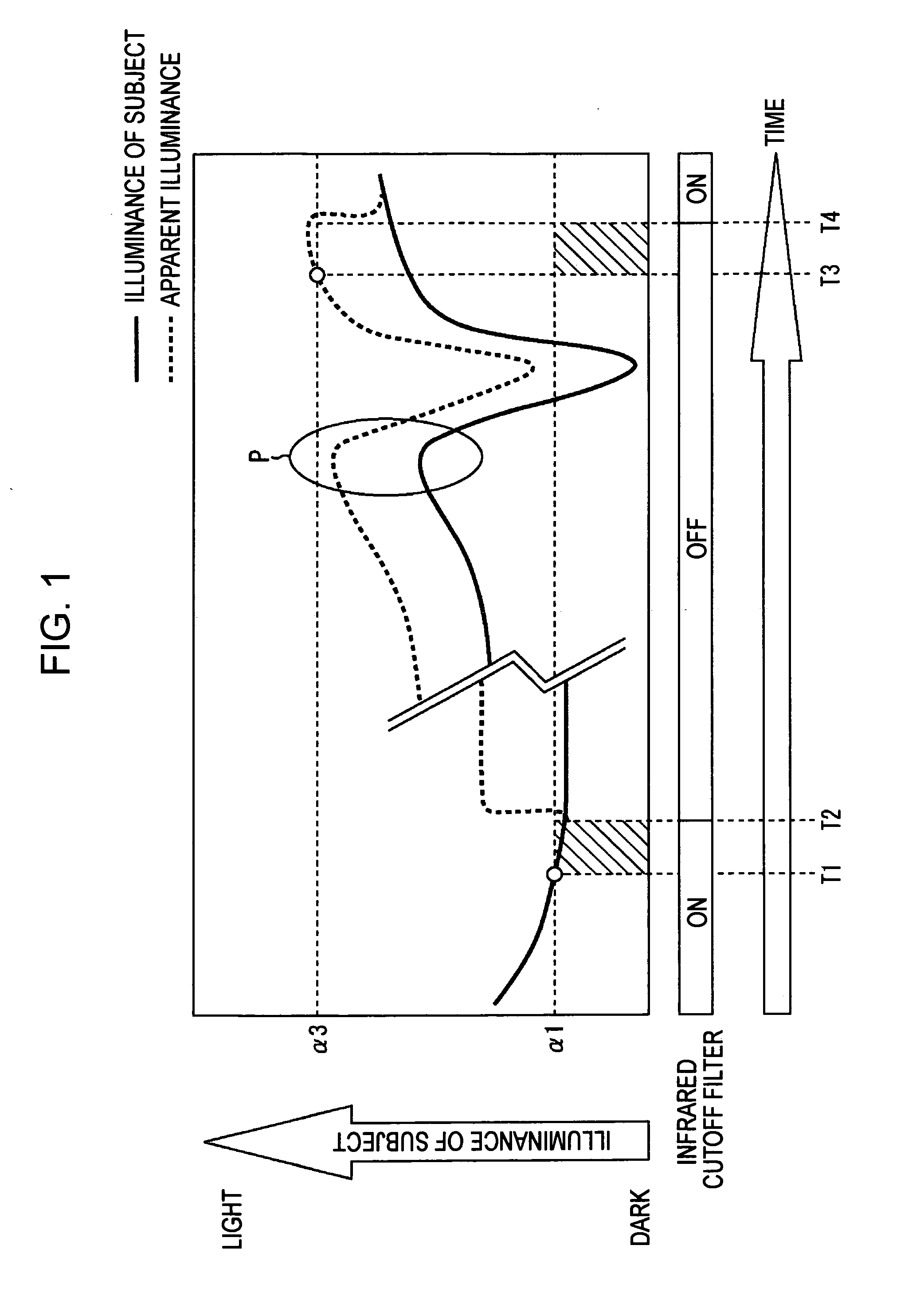
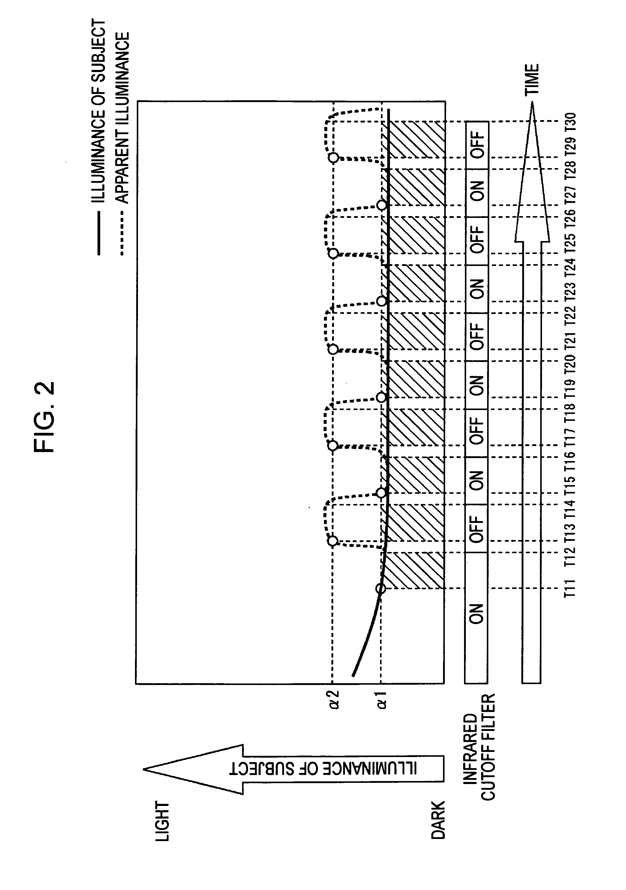
In the conventional monitor camera, as described above, when the infrared cutoff filter is controlled in accordance with the two threshold values, the two threshold values or the difference therebetween can become improper depending on the environment or the subject.
That is, it is difficult to properly set the threshold values and the difference therebetween, and this difficulty can cause an erroneous operation of the infrared cutoff filter.

Method used


Image

  • Imaging apparatus, and method and program for controlling an imaging apparatus
  • Imaging apparatus, and method and program for controlling an imaging apparatus
  • Imaging apparatus, and method and program for controlling an imaging apparatus

Examples


Embodiment Construction

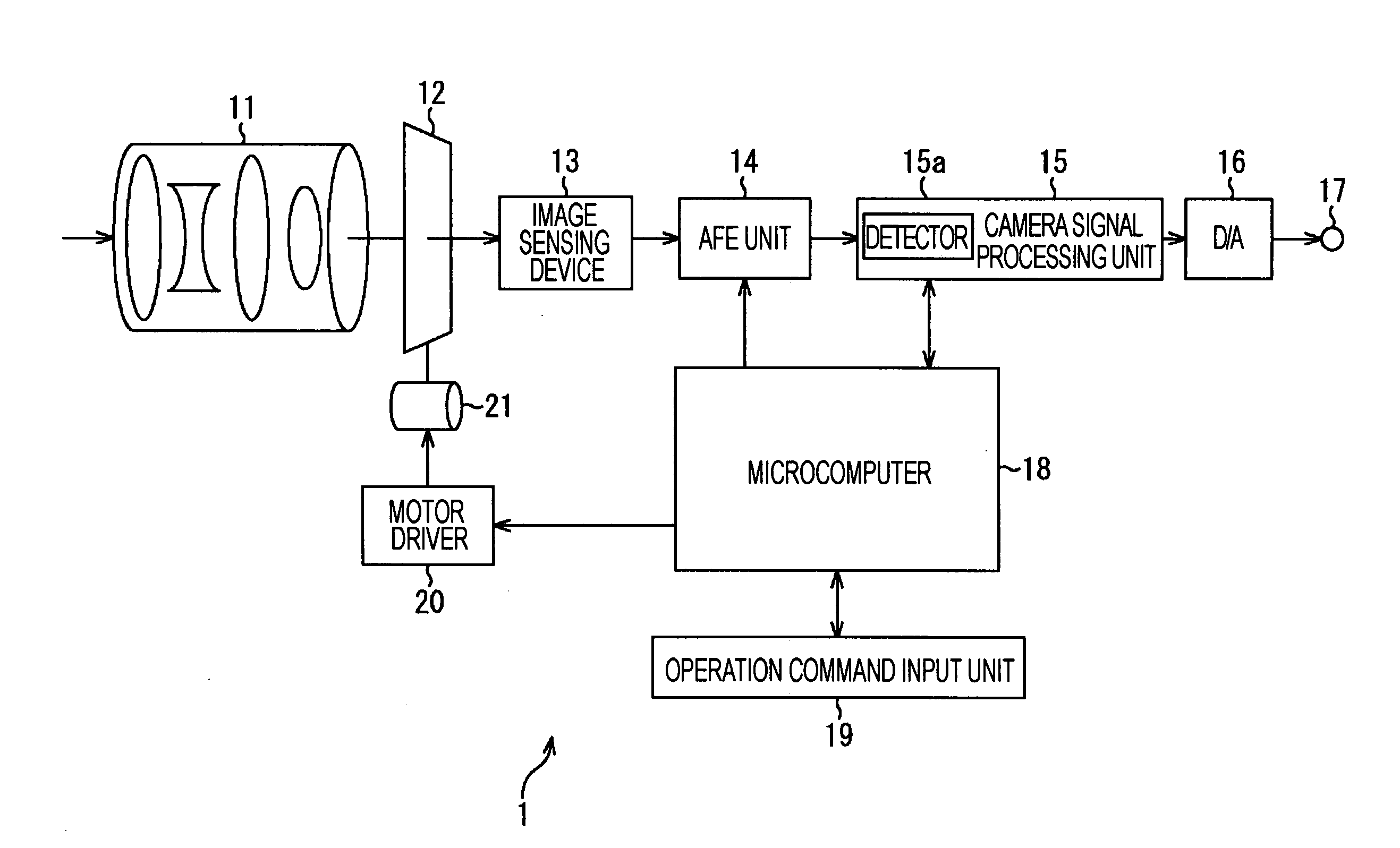
[0053] Before embodiments of the present invention are described, correspondence between specific examples of parts / steps in the embodiments and those in the respective claims is described. Note that the purpose of the following description is to indicate that specific examples corresponding to the respective claims are described in the embodiments, and thus the purpose of the following description is not to limit specific examples of the respective claims to those described below. That is, there can be a part / step that is not described in the following description of the correspondence but that corresponds to a part / step of a particular claim. Conversely, an example of a part / step, which is described in the following description as corresponding to a particular claim, can correspond to a part / step of another claim.

[0054] According to an embodiment of the present invention, there is provided an imaging apparatus (for example, a monitor camera 1 shown in FIG. 3) including an infrare...


PUM


Abstract

An imaging apparatus may include an infrared cutoff filter capable of being inserted into and extracted from an incident light path to an image sensing device, and may further include a first detecting unit configured to, when the infrared cutoff filter is off the incident light path to the image sensing device, detect whether the difference between current illuminance of a subject acquired from an image signal of the subject sensed by the image sensing device and a reference value of the illuminance of the subject determined after the infrared cutoff filter was extracted is equal to or greater than a first threshold value, and a filter control unit configured to, when the first detecting unit detects that the difference between the current illuminance and the reference value is equal to or greater than the first threshold value, insert the infrared cutoff filter into the incident light path.

Description

CROSS-REFERENCE TO RELATED APPLICATIONS [0001] This application claims priority from Japanese Patent Application No. JP 2006-020795 filed in the Japanese Patent Office on Jan. 30, 2006, the entire content of which is incorporated herein by reference. BACKGROUND OF THE INVENTION [0002] 1. Field of the Invention [0003] The present invention relates to an imaging apparatus and a method and program for controlling an imaging apparatus, and more particularly, to an imaging apparatus and a method and program for controlling an imaging apparatus, capable of providing an image in a highly stable manner in any environment of illumination, by correctly operating an infrared cutoff filter. [0004] 2. Description of the Related Art [0005] In a monitor camera, a sensor of the camera generally has high sensitivity in an infrared range. Therefore, in a usual environment in which subjects have high illuminance, an infrared cutoff filter is inserted into an optical path to cut off an infrared compone...

Claims


Application Information

Patent Timeline
Patent Type & Authority Applications(United States)
IPC IPC(8): G03B7/099G03B7/18G03B11/00H04N23/75
CPCH04N5/2254H04N5/33H04N5/238H04N23/75H04N23/20H04N23/55
Inventor KOBAYASHI, FUMIKAZUOHKAWA, JUN
Owner SONY CORP
Learn More