Surgical instrument for manipulating, positioning and fixing a surgical rod in relation to an implant

a surgical instrument and rod technology, applied in the field of surgical instruments, can solve problems such as thread damage, and achieve the effects of low cost, reliable fashion, and short tim

Active Publication Date: 2018-08-28
AESCULAP AG
View PDF14 Cites 0 Cited by
  • Summary
  • Abstract
  • Description
  • Claims
  • Application Information

AI Technical Summary

Benefits of technology

[0010]Starting from the previously described prior art, the invention is based on the object to allow a surgeon to carry out a manipulation, positioning and fixation of a surgical rod relative to an implant screwed in a bone or a bone piece, in particular a pedicle screw, in a reliable fashion and within short time. Here, in particular the process of screwing a fixation screw for the rod into the implant is to be facilitated. The instrument is supposed to be able to be manufactured by simple ways and means and at low costs and it should be easy to apply for the surgeon using it.

Problems solved by technology

This prevents the fixation screw from being obliquely screwed in the thread (cross-threading) which would mean that the thread might be damaged in some circumstance.

Method used


Image

  • Surgical instrument for manipulating, positioning and fixing a surgical rod in relation to an implant
  • Surgical instrument for manipulating, positioning and fixing a surgical rod in relation to an implant
  • Surgical instrument for manipulating, positioning and fixing a surgical rod in relation to an implant

Examples


first embodiment

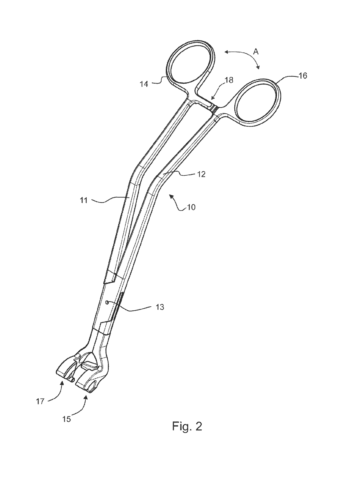
[0036]the instrument 10 is shown in FIG. 2. The instrument 10 is realized as a sort of pliers comprising two legs 11, 12 and is shown in the closed state in FIG. 2. The two legs 11 and 12 are coupled to each other with the aid of a hinge 13 so as to be able to rotate around the axis thereof. One end of the leg 11 comprises a finger eyelet 14 and the opposite end comprises a shaped working end 15 which is shown in detail in FIG. 3. One end of the leg 12 comprises a finger eyelet 16 and the opposite end comprises a shaped working end 17. In the area of the finger eyelets 14, 16, the legs 11, 12 are latched or can be latched with each other by means of a ratchet mechanism 18. Upon releasing the ratchet mechanism 18, the legs 11, 12 can be spread apart while the two working ends 15,17 move away from each other.

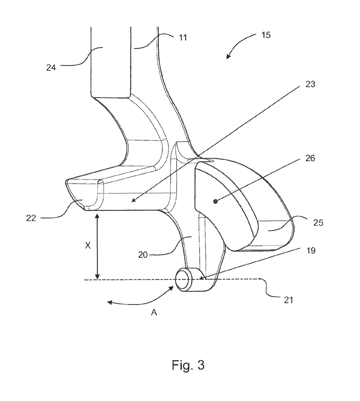
[0037]The direction of movement of the working ends 15 during opening and closing the instrument 10 is marked in FIG. 3 with a double arrow A. The working end 15 comprises a pin 1...

second embodiment

[0044]the invention in the form of an instrument 100 is shown in a schematic perspective illustration in FIG. 7. With the following exceptions, the instrument 100 is substantially identical to the instrument 10 shown in FIGS. 2 to 6. A curved protrusion 28 whose curvature extends around the pin 19 is formed only at the working end 15 of the leg 11. The protrusion 28 also has a curved guide track 29 the curvature of which extends around the pin 19 as the center. A bolt 30 of a guide unit 31 is guided in the guide track 29. The radius of the curvature of the guide track 29 corresponds to the distance between the axis of rotation of the instrument 100 around the head 4 (i.e. the longitudinal axis of the pin 19) and the mounting of the guiding means 31 in the guide track 29 (i.e. the longitudinal axis of the bolt 30). The bolt 30 can be translatorily shifted in the guide track 29 on the circular arc around the pin 19. As the bolt 30 has a round cross-section, it can also rotate around i...

third embodiment

[0048]the invention in the form of an instrument 110 is shown in FIG. 9 in a schematic perspective illustration. The instrument 110 is substantially the same as the instrument 100 of the FIGS. 7 and 8, with the exception that the bolt 30 does not have a round, but an elongated cross-section, so that it indeed is able to translatorily move along the guide track 29, but cannot be turned around its longitudinal axis. As a rotation of the guide unit 31 in the guide track 29 is not possible, its correct positioning so as to lie flat on the upper side of the head 4 of the pedicle screw 1, 2 is always ensured.

[0049]In a further embodiment not illustrated in the Figures but substantially corresponding to the embodiments of the FIGS. 7 to 9, the guide unit 31 is divided halfway. The one half of the guide unit 31 is guided in the guide track 29 of the leg 11. The other legs 12 also comprise a protrusion 28 including a guide track 29 where the second half of the guide unit 31 is guided in iden...


PUM


Abstract

A surgical instrument for manipulating and positioning a surgical rod relative to a surgical implant features two legs rotatably coupled to each other by a hinge. Each leg includes a working end. The working ends come into engagement with the implant upon closing the instrument by rotating the legs around the hinge and pivotally position the instrument relative to the implant around a swivel axis transverse to its longitudinal axis. At least one of the legs includes a contact structure for a surgical rod by which the rod is manipulated and positioned upon swiveling the instrument around the swivel axis relative to a rod seating of the implant. At least one of the legs includes a guide structure for guiding a fixation screw, to be screwed in, for the rod and/or for a tool for screwing in the fixation screw after having positioned the rod in the rod seating.

Description

RELATED APPLICATIONS[0001]This application is the United States National Phase Entry under 35 U.S.C. § 371 of International Application No. PCT / EP2014 / 067760, filed Aug. 20, 2014, which is related to and claims the benefit of priority of German Application No. DE 10 2013 109 058.3, filed Aug. 21, 2013. The contents of International Application No. PCT / EP2014 / 067760 and German Application No. DE 10 2013 109 058.3 are incorporated by reference herein in their entireties.FIELD[0002]The present invention relates generally to surgical instruments, and in particular to a surgical instrument by means of which a surgical rod can be manipulated, positioned and fixed relative to an implant, in particular relative to a pedicle screw.BACKGROUND[0003]The use of pedicle screws is commonly known in surgery. As a rule, they are used in combination with a rod in order to fix vertebral bodies relative to one another, for example. In doing so, the pedicle screws are turned into vertebral bodies which ...

Claims


Application Information

Patent Timeline
Patent Type & Authority Patents(United States)
IPC IPC(8): A61B17/70
CPCA61B17/7091A61B17/7086
Inventor FISCHER, KAYKRUGER, SVENMARX, IRENESCHNEIDER, LISA
Owner AESCULAP AG
Why Eureka
Try Eureka