
Three dimensional graphical user interface representative of a physical work space

a physical work space and user interface technology, applied in the field of user interfaces, can solve the problems of file name length, inability to store files sufficiently deeply within nested folders to truly reflect the desktop based model, and difficulty in us

Inactive Publication Date: 2007-08-16
FINLEY WILLIAM DEREK +1
View PDF17 Cites 71 Cited by
  • Summary
  • Abstract
  • Description
  • Claims
  • Application Information

AI Technical Summary

Benefits of technology

[0011] a first input device for receiving user input signals and for providing first control signals to the processor, the first input device for providing data indicative of at least a change in the viewpoint of the user; and, a first display for providing to the user an image generated by one of the plurality of software applications associated with a portion of the three dimensional virtual environment, t

Problems solved by technology

Though the model is convenient, it is often difficult to use due to system level constraints.
For example, Windows® a popular operating system provided by Microsoft® has limitations on file name length and, as such, is sometimes unable to store files sufficiently deeply within nested folders to truly reflect the desktop based model.
Further, since some systems are more limited than others, the model when implemented results in some limitations on portability.
For many applications and for application execution, the desktop model is often poor.
Also, though the desktop model is well suited to providing user references for many different functions, it is poorly suited for organizing large volumes of data since it has no inherent organizational structure other than one set by a user.
Thus, similar to actual physical desktops, some virtual desktops are neat and organized while others are messy and disorganized.
Unfortunately, with the wide adoption of the World Wide Web and with significant attempts to get around search engine technology—to “fool” the search engines—it is often difficult to significantly reduce a search space given a particular query.
Unfortunately, the desktop model, which has been beneficial to the widespread acceptance of personal computers generally, is often insufficient for effective organization of data and applications within organizations, distributed environments and handling large amounts of information.

Method used


Image

  • Three dimensional graphical user interface representative of a physical work space
  • Three dimensional graphical user interface representative of a physical work space
  • Three dimensional graphical user interface representative of a physical work space

Examples


first embodiment

[0029] Referring to FIG. 2A, shown is a simplified diagram according to a first view of the invention. Shown is a simplified image representing a first view of the user's virtual workspace 201 as modeled after a typical office. The virtual workspace 201 as displayed includes a virtual desk 205, which comprises a virtual desktop element 202 and personal computer 209. Also shown are a virtual filing cabinet 203 and, a virtual telephone 204. Further, a virtual recycle bin 206, a virtual alarm clock 207, and a virtual printer 208 are within the virtual space 201.

[0030] As is evident to those of skill in the art, a user interface based on the virtual space provides a two-dimensional view of a portion of the space—a viewport. Navigation tools may allow a user to navigate throughout the space in order to change their current viewport. For example, during typical work, a user sets the viewport to the virtual desktop 202 of their virtual desk 205. In use, the virtual desktop 202 provides muc...

second embodiment

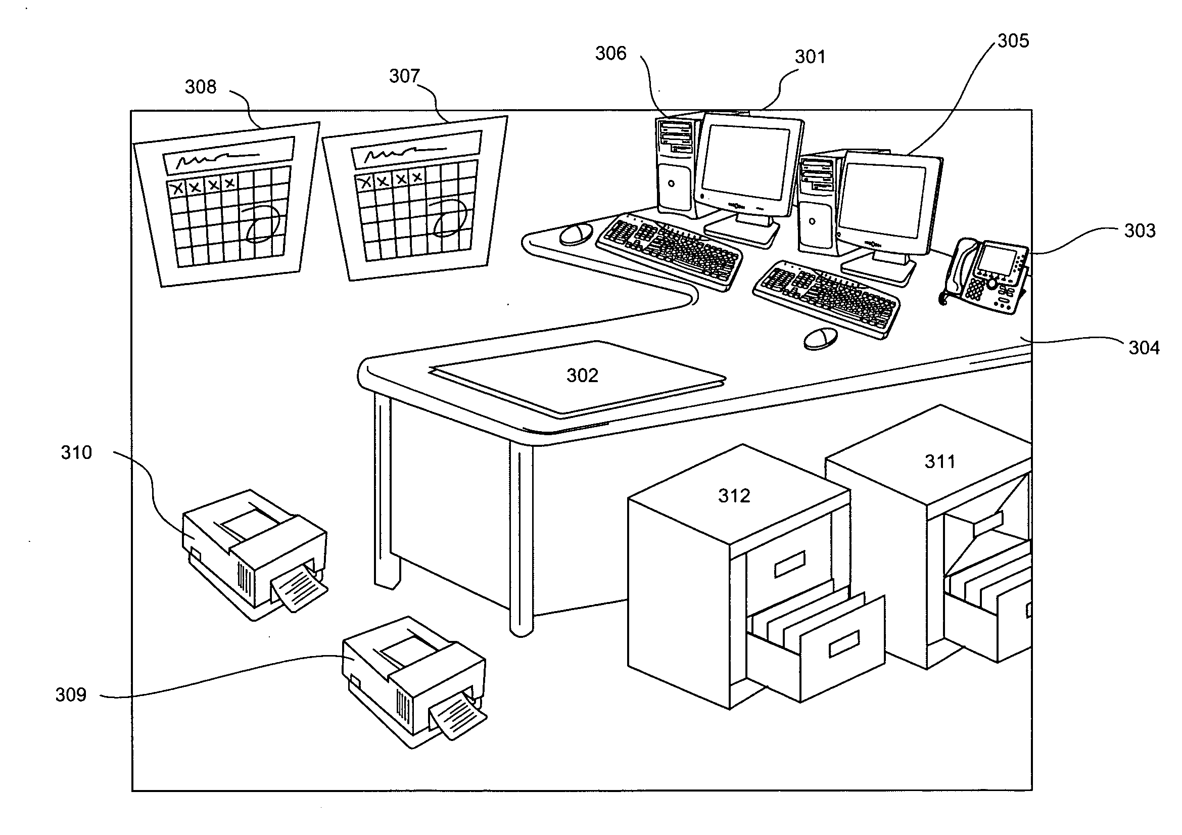
[0045] Referring to FIG. 3 shown is a second embodiment wherein the user has established shortcuts or aliases onto the virtual desktop. Shown is a virtual desktop 301 upon which the user has merged shortcuts or aliases for items, which may be external to their immediate environment but are frequently accessed or utilized. As such the virtual desktop contains the users virtual desktop 302, their virtual telephone 303, virtual desk 304, their virtual personal computer 306, their virtual calendar 307 and personal filing cabinet 311.

[0046] Additionally the user has added shortcuts as follows:

[0047] virtual computer 305, which for example could be a server that the user is responsible for maintaining, a remote computer within a laboratory performing tests under the users direction, or a variety of other advantageous links to additional computers;

[0048] second virtual calendar 308, which for example could be the merged vacation records for the users team, bookings for a conference room ...

third embodiment

[0053] Referring to FIG. 4A and FIG. 4B shown is a third embodiment wherein the user is now able to leverage the virtual desktop with multiple monitors. Shown in FIG. 4A is a simplified diagram corresponding to a first virtual desktop image 400 provided on a first monitor. Referring to FIG. 4B a simplified diagram corresponding to a second virtual desktop image 402, this second virtual desktop image 402 being displayed on a second physical monitor. In the embodiment described herein the view provided on the first monitor is responsive via an input signal associated with the second monitor and the users actions on the said monitor in defining a view. Alternately, the two images may be completely decoupled with one monitor being the personal desktop of the user and the second monitor being a view of an overall manufacturing environment wherein the users viewport on this second monitor adjusts according to their actions on said second monitor.

[0054] Thus, for example, a user stores a s...


PUM


Abstract

A three-dimensional user interface is described in which applications are accessed via user interaction with images of three dimensional shapes providing on a display of a computing device. A user is able to adjust their viewpoint within a virtual three dimensional environment. The user interface provides an efficient and intuitive way of managing a large number of applications.

Description

FIELD OF THE INVENTION [0001] This application claims benefit of U.S. Provisional Patent Application No. 60 / 762,128 filed Jan. 26, 2006 and No. 60 / 762,514 filed Jan. 27, 2006, the entire contents of which are incorporated herein by reference. [0002] The present invention relates to User Interfaces and more particularly to a method and system for providing a user interface operable for applications including operating systems.BACKGROUND OF THE INVENTION [0003] Data access and retrieval has always been an important aspect of computers. Different data retrieval and data display models have been proposed over the years, but most system designers return to one of three methods due to their simplicity, ease of use, and user comprehensible models. These three models include the desktop model, the list based model, and the hierarchical list model. [0004] The desktop model popularized by Apple® with its Macintosh® computers is used to display computer operating system data in a virtual deskt...

Claims


Application Information

Patent Timeline
IPC IPC(8): G06F3/048
CPCG06F3/04815
Inventor FINLEY, WILLIAM DEREKDOYLEND, CHRISTOPHER WILLIAM
Owner FINLEY WILLIAM DEREK
Learn More