Ergonomic device

a technology of ergonomics and grips, applied in the field of ergonomics, can solve the problems of uncomfortable use for long periods, round tip and suffer the same gripping problems, so as to achieve less gripping force and improve comfor

Inactive Publication Date: 2007-08-23
PACIFIC WRITING INSTR
View PDF0 Cites 22 Cited by
  • Summary
  • Abstract
  • Description
  • Claims
  • Application Information

AI Technical Summary

Benefits of technology

[0010] The objects of the present invention are to provide an ergonomic handle for a variety of hand-held devices, including a pencil, a highlighter, and a cutting tool. The design provides the advantages of requiring less gripping force to hold for improved comfort; securely cradles the tips of the thumb and fingers for preventing slipping; and can be pressed onto the writing surface by the base of the index finger.

Problems solved by technology

Therefore, they are uncomfortable to use for long periods.
The tip is round and suffers the same gripping problems as a conventional pen.
However, the tip is round and suffers the same gripping problems as a conventional pen.
The sides of the pen are cylindrical, and suffers the same gripping problems as a conventional pen.
Further, the tip is cylindrical, and suffers the same gripping problems as a conventional pen.
The tip is round and suffers the same gripping problems as a conventional pen.

Method used


Image

  • Ergonomic device
  • Ergonomic device
  • Ergonomic device

Examples


first embodiment

[0033]FIGS. 10 and 11 show a first embodiment according to the present invention, employing an ergonomic handle similar to that shown in FIGS. 1-9. In this case, instead of a pen, the working end of the instrument is a porous tip marker 105, such as a highlighter, permanent ink marker, water color marker, or the like. A removable cap 106 is provided which snaps over the tip of the marker 105. Alternately, the marker may be retractable, having an ink suitable for this application. The ink for the marker is contained within the body 10 of the handle, for example using the entire space within the body as a reservoir, or a central portion only. The reservoir is typically filled with a fibrous material or sponge to keep the ink from frothing and to damp waves. Likewise, the material may act as a wick, or a separate wick may be provided. The cap 106 has a rim 102 which snaps over the edge 101 of the body 10. The cap 106 has a cylindrical bore 104 in which the ferrule 103 from which the ma...

second embodiment

[0037] FIGS. 12A-G show the invention, which provides a sequential feed pencil. See, U.S. Pat. Nos. 4,966,478, 5,292,202, 6,161,976, 3,790,291, 3,898,009 expressly incorporated by reference.

[0038] As shown in FIGS. 12A-G, the pencil includes a conduit 110 formed centrally within the body 10, having therein a set of stacked writing elements 112, each comprising a presharpened lead 114 surrounded by a ferrule 116, wherein the ferrules are stackable within the inner tube 114. The ferrule 116 is hollow in the rear, such that the lead 114 of a succeeding writing element 112 fits within the ferrule 116 of the preceding writing element 112. The ferrule 116 is friction fed into the conduit 110, such that pressure on the first lead 114′ does not cause the ferrule 116′ of the first writing element 112′ to recede into the conduit 110. In order to replace an exhausted or broken lead 114′, the first writing element 112′ is extracted from the tip, and pushed into the back of the conduit 110, forc...

third embodiment

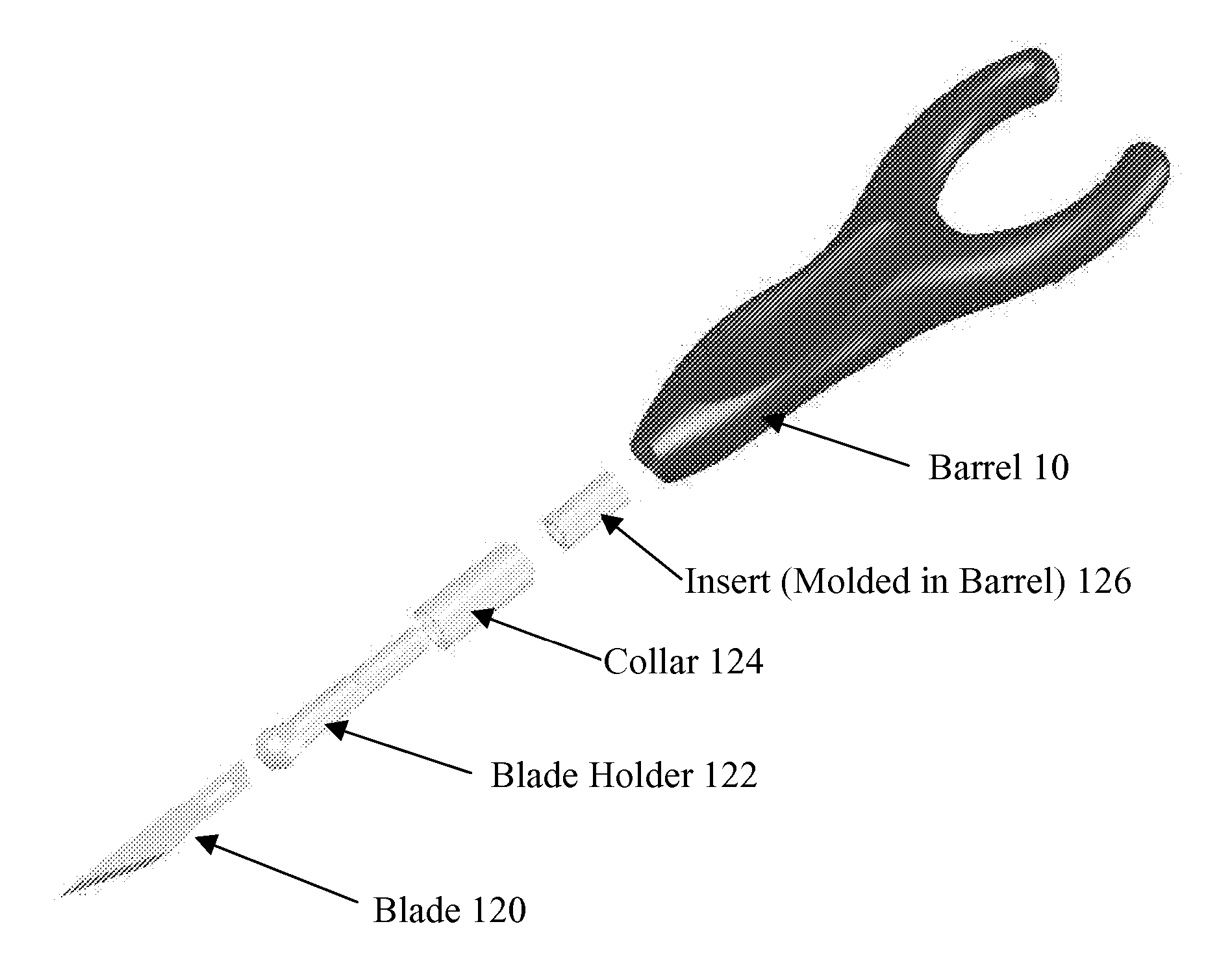
[0040]FIGS. 13-15 show the invention, which provides an ergonomic handle cutting tool. See, U.S. Pat. No. 4,071,952 (Meshulam, et al.), U.S. Pat. No. 6,328,494 (Moxon), and U.S. Pat. No. 2,619,724, expressly incorporated by reference. A knife shown in FIG. 13, consists of an ergonomically adapted handle, as described in FIGS. 1-9, which may be solid plastic or metal (e.g., aluminum) 10 having a blade receiving end with a diameter of about five-sixteenths inch. A blade 120 is detachably secured to one end of the handle by a chuck comprising a blade holder 122, in which the blade 120 is locked by a collar 124. An insert 126 is molded into the barrel of the body 10, which holds the blade holder 122 within the barrel of the body 10.

[0041] The blade 120 is, for example, an X-Acto® Hobby No. 11 Knife blade, although the blade itself is replaceable and does not limit the invention. A kit of blades may be provided with the handle.

[0042] A variety of tool attachment means 12 can be employed...


PUM


Abstract

An ergonomic instrument is comprised of an elongated body with a writing tip or tool at the lower end, and an upper end for supporting the base of the index finger. Arcuate arms extending up from the upper end of the body are arranged for being positioned on the sides of the index finger. A concave front groove is arranged along the front side of the body for cradling the tip of the index finger. Concave side grooves are arranged along the sides of the body for cradling the tips of the thumb and middle finger. Forwardly protruding ears are arranged between the front and respective sides for being pinched between the index finger and the thumb, and between the index finger and the middle finger.

Description

RELATED APPLICATIONS [0001] The present application is a non-provisional of, and claims benefit of priority from, U.S. Provisional Patent Application 60 / 749,524, filed Dec. 12, 2005, expressly incorporated herein by reference.BACKGROUND OF THE INVENTION [0002] 1. Field of the Invention [0003] This invention relates generally to ergonomic grips for hand-held instruments. [0004] 2. Prior Art [0005] U.S. Pat. No. 6,637,962, expressly incorporated herein by reference, discloses an ergonomic pen having a wishbone-shaped body. [0006] Conventional straight writing instruments such as ink pens, ball point pens, and pencils have straight and narrow cylindrical bodies. The lower portion of a typical writing instrument is arranged to be held between the tips of the thumb, index finger, and middle finger. The upper portion of the pen is arranged to rest between the bases of the thumb and index finger. The narrow round bodies of conventional writing instruments require a relatively firm grip to ...

Claims


Application Information

Patent Timeline
Patent Type & Authority Applications(United States)
IPC IPC(8): A46B5/04A46B5/02
CPCB26B5/00B43M11/06B43K7/005B43K8/003B43K21/003B43K21/006B43K23/004B43K23/008B43K24/026B43K24/04B43K27/04B43K29/02B43L19/0018B43L19/0068B43K5/005
Inventor ROCHE, COLINRONSSE, ROBERT
Owner PACIFIC WRITING INSTR
Why Eureka
Try Eureka