
Low projection inserts for rock bits

Active Publication Date: 2007-02-15
BAKER HUGHES INC
View PDF17 Cites 2 Cited by
  • Summary
  • Abstract
  • Description
  • Claims
  • Application Information

AI Technical Summary

Benefits of technology

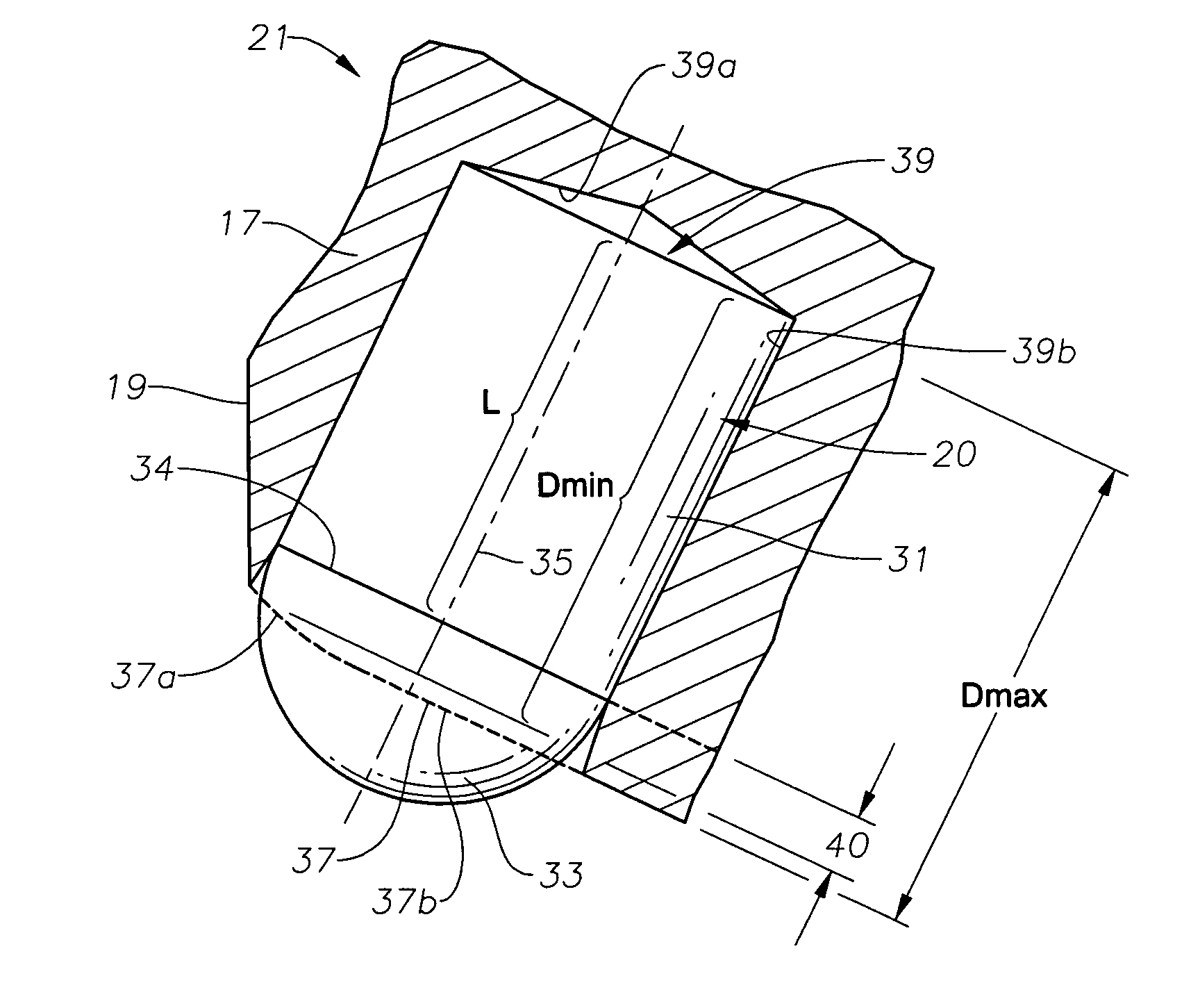
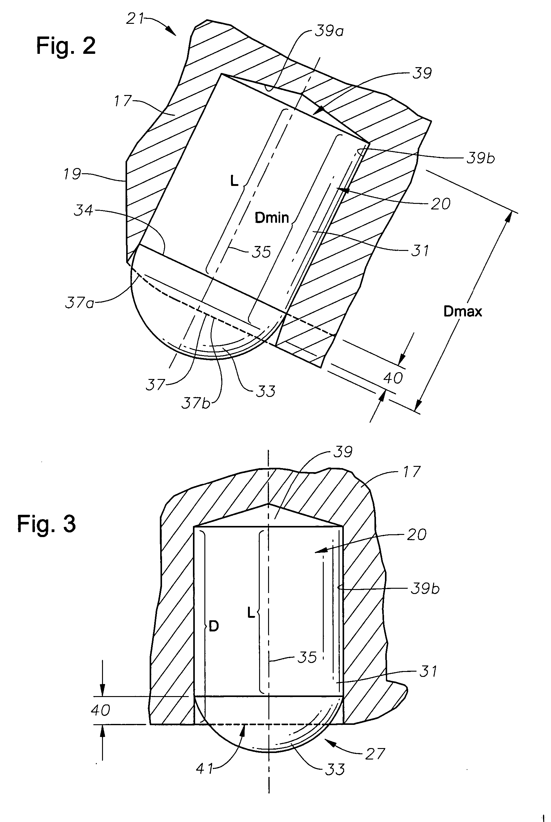
[0007] During the press-fit procedure, an entry portion of the hole is distorted. The distorted entry zone is slightly enlarged relative to the remainder of the hole. As a result, the distorted entry zone provides less gripping force than the remainder of the hole. In this invention, at least a majority of the distorted entry zone is above the barrel and encircles part of the cutting tip. As a result, the barrel experiences the full designed gripping force throughout its length. Inspections have determined that the entry zone is typically about 0.080 inch in depth. Preferably, the minimum difference between the barrel length and the sidewall depth is 0.080 inch.
[0008] The holes for the outer row may be d

Problems solved by technology

These inserts are more subject to breakage due to high bending forces imposed on the inserts.
Inserts are made less resistant to breakage by increasing the toughness, but this decreases the hardness.
A decreased hardness generally results in the insert wearing faster in hard formations.
However, in the prior art, it has been generally considered that reduced insert projection reduces the rate of penetration.
Also, the loss of inserts, even with a shorter cutting tip, still occurs.

Method used


Image

  • Low projection inserts for rock bits
  • Low projection inserts for rock bits
  • Low projection inserts for rock bits

Examples


Embodiment Construction

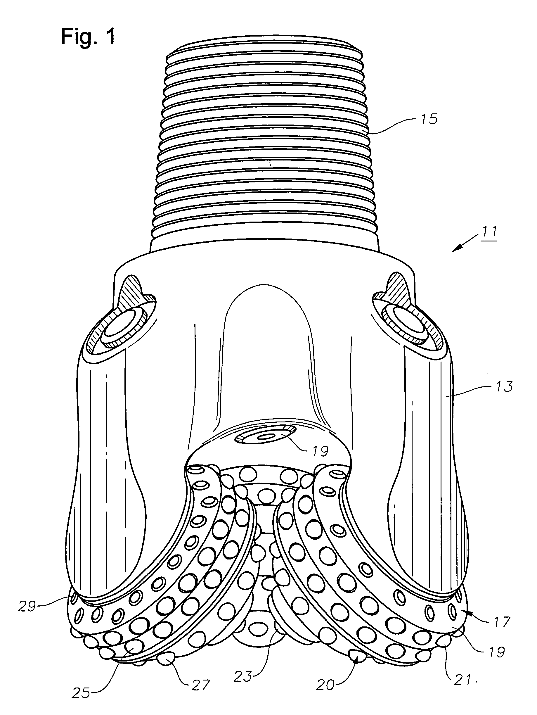
[0013] Referring to FIG. 1, bit 11 has a body 13 with a threaded pin 15 on the upper end for connection to a drill string. At least one cone, and typically three cones 17, are rotatably mounted on bearing pins (not shown) that extend from bit legs of body 13.

[0014] Each cone 17 has a generally conical exterior with a gage surface 19 on its outer end and a nose area 23 on its inner end. A plurality of inserts 20, shown schematically in FIG. 1, are mounted and protrude from the exterior surface of each cone 17. Each cone 17 has an outer or heel row 21 of inserts 20, an adjacent row 25 of inserts 20 located next to outer row 21, and one or more inserts 20 in the nose area 23. In this embodiment, each cone 17 also has an inner row 27 located between nose area 23 and adjacent row 25. Gage inserts 29, each having a flat top, are mounted to gage surface 19.

[0015] Referring to FIG. 2, each insert 20, regardless of where it is located, has a cylindrical barrel 31 and an integral cutting ti...


PUM


Abstract

An earth boring bit has an outer row of inserts located within extra deep holes. Each of the holes has a cylindrical sidewall with a depth greater than the length of the barrel of the insert mounted within. The difference in depth is at least equal to a distorted entry zone in the hole. A portion of the sidewall that includes the entry zone surrounds the cutting end, reducing the projection of the cutting end from the land.

Description

BACKGROUND OF THE INVENTION [0001] One type of earth boring bit has cones that rotate as the bit revolves around a bit axis. Each cone has a number of rows of cutting elements. In one type, the cutting elements comprise tungsten carbide inserts pressed within holes formed in the exterior surface of the cones. Each insert has a cylindrical barrel that fits in an interference fit in one of the holes. A cutting end or tip is integrally formed with the barrel and protrudes from the hole. The cutting tip may be of a variety of configurations, such as hemispherical, ovoid, or chisel-shaped. [0002] Typically, in the prior art, the holes are drilled in annular lands formed on the exterior of the cone. The land is normally cylindrical or conical. The depth of the hole sidewall normally equals the length of the barrel. The land is thus flush with the junction between the barrel and the cutting tip. The entire cutting tip protrudes from the land. [0003] In some bit cones, part of the holes may...

Claims


Application Information

Patent Timeline
IPC IPC(8): E21B10/36
CPCE21B10/16E21B17/1092E21B10/50
Inventor FELDERHOFF, FLOYD C.BAKER, BRIAN A.PESSIER, RUDOLF C.EASON, JIMMY W.
Owner BAKER HUGHES INC
Learn More