Eureka AIR delivers breakthrough ideas for toughest innovation challenges, trusted by R&D personnel around the world.

Motorized Pulley With Cable Connector

Active Publication Date: 2007-08-23
INTERROLL HLDG
View PDF3 Cites 14 Cited by
  • Summary
  • Abstract
  • Description
  • Claims
  • Application Information

AI Technical Summary

Benefits of technology

[0016] According to a further preferred embodiment of the invention the cable connector is a male connector with the conductors situated in a recess at the end of the shaft. The cable connector being c

Problems solved by technology

However, in some particular cases problems occur in that large production tolerances occur in the individual parts (cable connector (male connector) / female connector and shaft cap).
Thereby the problem occurs of conveying the female connector through the opening in the shaft cap and engaging the female connector and the cable connector (the male connector), and finally securing the female connector reliably to the shaft cap by means of the fastening screw.
In these particular cases it may involve that the parts must be forced together with ensuing damage to the individual parts, including the cable connector.
Of course, this is inconvenient and involves that a number of combinations of cable connectors and female connectors must be tried to find the combination where the tolerances in cable connection and female connection are within acceptable values.
In connection with the manufacture of the motorized pulley this combination task can be performed with some difficulty, but in those cases where an already installed motorized pulley is to be exchanged, eg in connection with a renovation task, it will be practically impossible to have to test one's way through various motorized pulleys until the correct combination of cable connector and female connector is found.
Alternatively the connector must be forcibly compressed with an ensuing risk of damaging connector and its conductors.

Method used


Image

  • Motorized Pulley With Cable Connector
  • Motorized Pulley With Cable Connector
  • Motorized Pulley With Cable Connector

Examples


Embodiment Construction

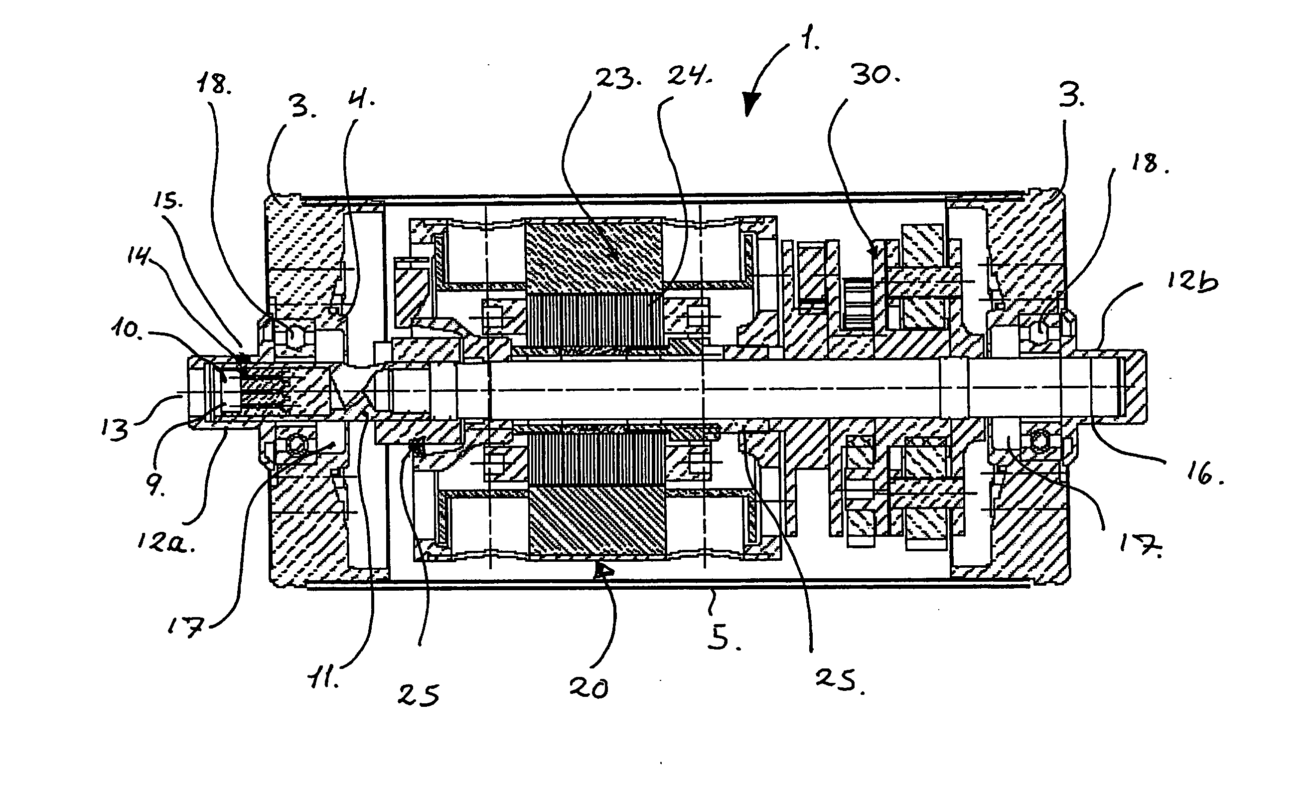
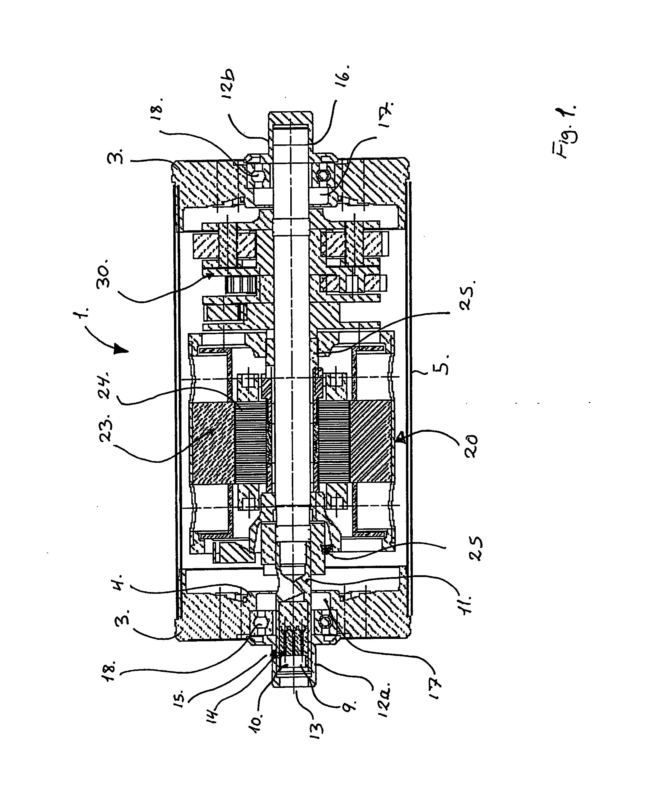
[0023] Thus, FIG. 1 shows a motorized pulley 1 (an electrically operated roller) with a cable connector 10 according to the invention. Such motorized pulley 1 lends itself for use in connection with ie material handling systems, including roller conveyors and endless conveyor belts, packaging systems, logistics systems for goods and luggage, and check-out counters.

[0024] The motorized pulley 1 comprises a cylindrical drum 5 (jacket) or an essentially cylindrical drum 5 that is mounted rotatably on a stationary shaft 11 at end caps 3 that are secured at the end of the drum 5. Each end cap 3 comprises a centrally configured hub 4, in which a roller or ball bearing 18 is configured and through which the stationary shaft 11 is conveyed. The hub 4 moreover comprises a sealing (compression packing) 17 for establishing a sealing connection between the hub 4 and the shaft 11, whereby a liquid-proof sealing is provided between the interior of the motorized pulley 1 and the surroundings. At ...


PUM


Abstract

The present invention relates to a motorized pulley (1) with a cylindrical cable connector (10) comprising a cylindrical drum (5) that is mounted rotatably about a shaft (11) and is configured for being fixedly mounted on supporting means, said cylindrical drum (5) delimiting an interior space intended for receiving an electric motor (20) for producing a rotating movement of the drum about the shaft (11), and wherein said shaft comprises a cylindrical recess (9) configured at an end of the shaft (11) for receiving the cylindrical cable connector (10) that is electrically coupled to said electric motor (20). Hereby a motorized pulley is accomplished that has a cable connector able to allow for tolerances deriving from the manufacture of the individual parts and mounting tolerances in the motorized pulley with the cable connector.

Description

BACKGROUND OF THE INVENTION [0001] 1. Field of the Invention [0002] The present invention relates to a motorized pulley with a cable connector. [0003] 2. Description of the Related Art [0004] Motorized pulleys are known in a number of contexts and are used ie material handling equipment, including roller conveyors and endless conveyor belts, packaging systems, logistic systems for goods and luggage and check-out counters. [0005] EP 0 752 970 B1 teaches a motorized pulley having an integral electrical connector at the end of the shaft and for being connected to an electric power source. The motorized pulley comprises a cylindrical drum which is rotatably mounted on a stationary roller shaft. An electric motor and a gear are arranged within the drum and are connected to the shaft for producing rotation of the drum about the shaft. At the end of the shaft, a recess is provided for receiving a connector assembly that is electrically coupled to the electric motor. The connector is config...

Claims


Application Information

Patent Timeline
IPC IPC(8): H01R3/00B65G23/08H01R13/631H02K5/22
CPCH01R13/6315H02K7/1012H02K5/225
Inventor HVIDBERG, JENSJENSEN, JAN STOVRING
Owner INTERROLL HLDG
Why Eureka
Eureka Blog
Learn More