Floating optic accommodating intraocular lens

a technology of optics and lenses, applied in intraocular lenses, eye implants, medical science, etc., can solve the problems of limited materials from which the lens is made, the lens could be folded, and the fixation of the lens not well in the capsular bag

Inactive Publication Date: 2007-08-23
C& C VISION INT
View PDF62 Cites 30 Cited by
  • Summary
  • Abstract
  • Description
  • Claims
  • Application Information

AI Technical Summary

Problems solved by technology

These lenses could be folded but did not fixate well in the capsular bag, but resided in pockets between the anterior and posterior capsules.
The advent of an acco

Method used


Image

  • Floating optic accommodating intraocular lens
  • Floating optic accommodating intraocular lens
  • Floating optic accommodating intraocular lens

Examples


Embodiment Construction

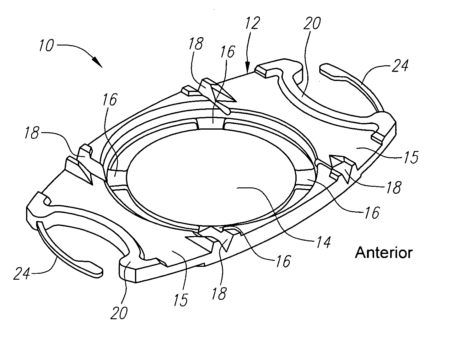
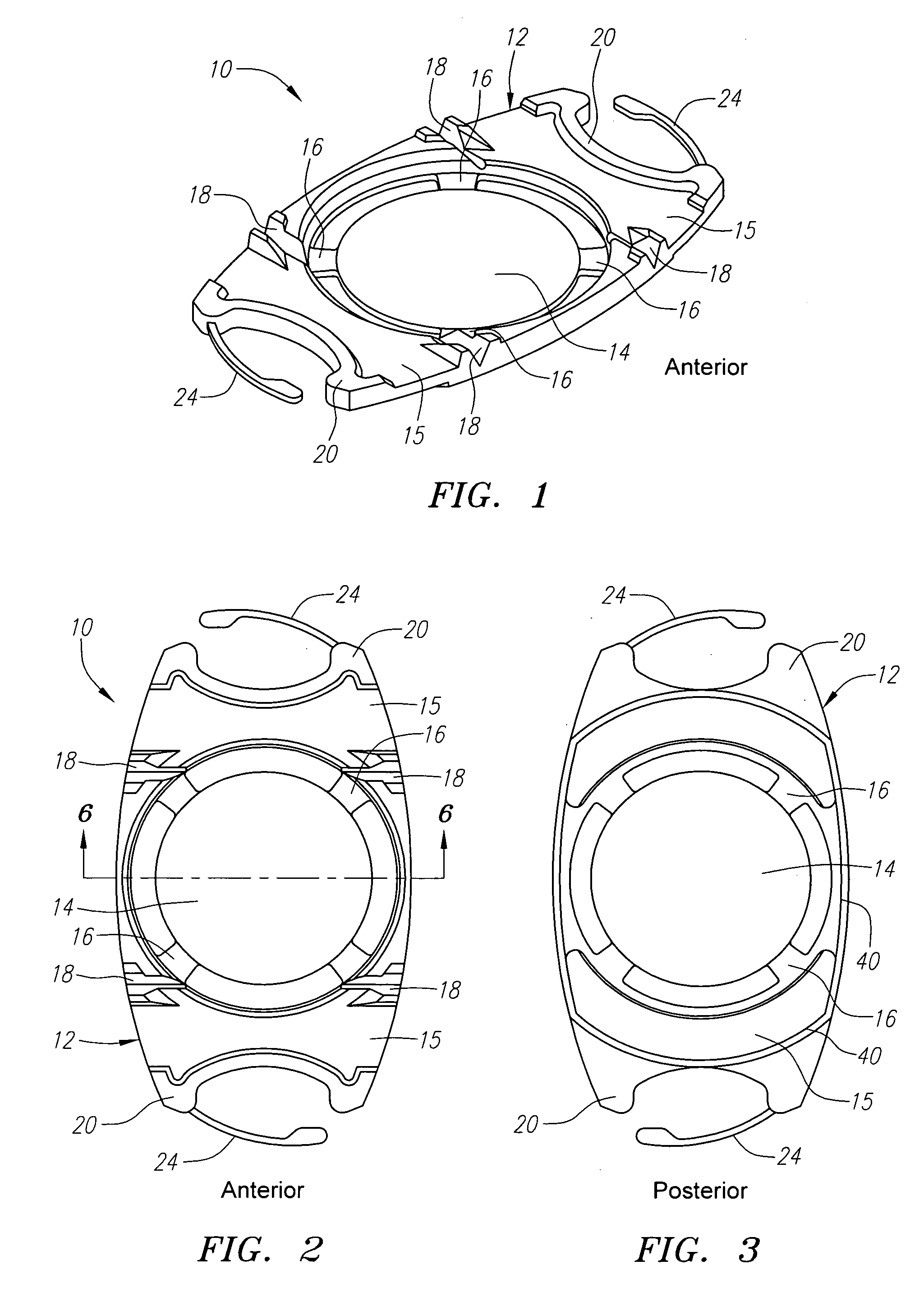
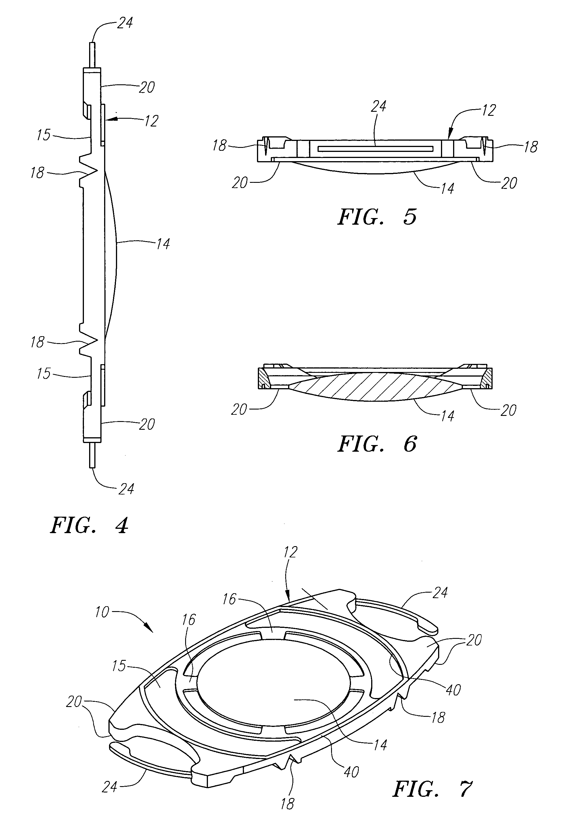
[0014] Turning now to the drawings, FIG. 1 is a perspective view of the present lens 10 including a lens body or plate 12 and optic 14. The body 12 includes haptics 15. The body 12 and optic 14 are formed of silicone or other suitable flexible material. Flexible straps 16 are provided between the body 12 and the periphery or outer diameter of the optic 14. The straps may be 0.5 mm long in the radial direction and 0.1 mm thick so as to essentially create an “piston optic”14 supported by the straps. In yet another iteration the lens may have a continuous skirt surrounding the optic and connecting the optic to the lens body. The optic 14 typically can have a diameter of 4.5 mm, a typical width of the overall lens 10 on the short side is 6.1 mm and the typical length from end to end (not including fixation fingers) on the long side is 10.5 mm.

[0015] The body 12 and optic 14, as well as outer thickened footplate ends 20, are formed of silicone or other suitable flexible material. The le...


PUM


Abstract

An accommodating intraocular lens comprising a flexible body, a flexible optic which is moveable anteriorly and posteriorly relative to the lens body, and a weakened portion connecting the optic to the body. The body may have extending centration and fixation loops on its distal ends.

Description

BACKGROUND [0001] Intraocular lenses have for many years had a design of a single optic with loops attached to the optic to center the lens and fixate it in the empty capsular bag of the human eye. In the mid '80s plate lenses were introduced, which comprised a silicone lens, 10.5 mm. in length, with a 6 mm. optic. These lenses could be folded but did not fixate well in the capsular bag, but resided in pockets between the anterior and posterior capsules. The first foldable lenses were all made of silicone. In the mid 1990s an acrylic material was introduced as the optic of lenses. The acrylic lens comprised a biconvex optic with a straight edge into which were inserted loops to center the lens in the eye and fixate it within the capsular bag. [0002] Recently accommodating intraocular lenses have been introduced to the market, which generally are modified plate haptic lenses and, like the silicone plate haptic lenses, have no clear demarcation between the junction of the plate with t...

Claims


Application Information

Patent Timeline
IPC IPC(8): A61F2/16
CPCA61F2/1613A61F2250/0018A61F2002/1689A61F2/1694A61F2002/169A61F2/1635A61F2/1629A61F2/16
Inventor CUMMING, J. STUARTDELL, STEVEN J.SOISETH, JONATHAN R.
Owner C& C VISION INT
Why Eureka
Try Eureka