Method and apparatus for improving vision and the resolution of retinal images
What is AI technical title?
AI technical title is built by Patsnap AI team. It summarizes the technical point description of the patent document.
a retinal image and resolution technology, applied in the field of retinal image resolution and vision improvement, can solve the problems of impairing vision, ophthalmic lenses that can only correct defocus and astigmatism, blur images taken of the living human retina, etc., and achieve the effect of accurately measuring higher-order aberrations
Inactive Publication Date: 2006-03-02
UNIVERSITY OF ROCHESTER
View PDF62 Cites 126 Cited by
Summary
Abstract
Description
Claims
Application Information
AI Technical Summary
This helps you quickly interpret patents by identifying the three key elements:
Problems solved by technology
Method used
Benefits of technology
Benefits of technology
[0008] In view of the foregoing, it is apparent that there exists a need in the art for a method of and an apparatus for producing ophthalmic optical elements that provide improved or supernormal vision over that which is currently available, as well as high resolution retinal images. It is, therefore, a primary object of the present invention to provide a method of and an apparatus for accurately measuring higher order aberrations of the eye and for using the data thus measured to compensate for those aberrations with a customized optical element.
[0009] It is also an object of the present invention to provide an improved wavefront sensor which rejects light reflected from structures other than the retina and which is capable of providing a complete measurement of the eye's aberrations.
[0011] It is likewise a primary object of the present invention to provide a method of and an apparatus for producing high resolution retinal images which allow the imaging of microscopic structures the size of single cells in a human retina.
[0012] Briefly described, these and other objects of the invention are accomplished by providing a system for receiving light reflected from a retina of an eye. The wavefront in the plane of the pupil is recreated in the plane of a lenslet array of a Hartmann-Shack wavefront sensor. Each of the lenslets in the lenslet array is used to form an aerial image of the retinal point source on a CCD camera located adjacent to the lenslet array. The wave aberration of the eye, in the form of a point source produced on the retina by a laser beam, displaces each spot by an amount proportional to the local slope of the wavefront at each of the lenslets. The output from the digital CCD camera is sent to a computer which then calculates the wave aberration and provides a signal to a deformable mirror. Following an iterative procedure, the deformable mirror ultimately acquires a shape that is identical to the wave aberration measured at the outset, but with half the amplitude. This deformation is the appropriate one to flatten the distorted wavefront into a plane wave, which improves image quality.
Problems solved by technology
Despite significant advances in spectacle and contact lens design, current ophthalmic lenses still can only correct defocus and astigmatism.
These high order aberrations of the eye not only blur images formed on the retina, which impairs vision, but also blur images taken of the living human retina.
There have been two obstacles that prevent the use of specially-designed optical elements to correct aberrations beyond defocus and astigmatism in the eye.
First, quantitative measurement of the irregular aberrations of the eye has not been possible.
Second, a mechanism to correct the monochromatic aberrations of the eye other than defocus and astigmatism has not been demonstrated.
They cannot measure the complete wave aberration of the eye, which includes all aberrations left uncorrected by conventional spectacles.
Moreover, rapid, automated computation of the wave aberration has not been demonstrated with this method.
That description is generally insufficient to accurately compute the optical performance of the eye.
This instrument was not equipped to remove unwanted light reflected from other surfaces, such as lenses and the cornea of the eye.
That approach, however, suffers from the fundamental problem that the wave aberration of the eye depends on the combined effects of refractive index variations throughout the eye's optics.
The use of an optical element to correct monochromatic aberrations higher than second order has never been achieved.
In both those systems, no appropriate method for measuring the eye's high order aberrations was disclosed.
Method used
Image
Click on the blue label to locate the original text in one second.
Reading with bidirectional positioning of images and text.
Examples
Embodiment Construction
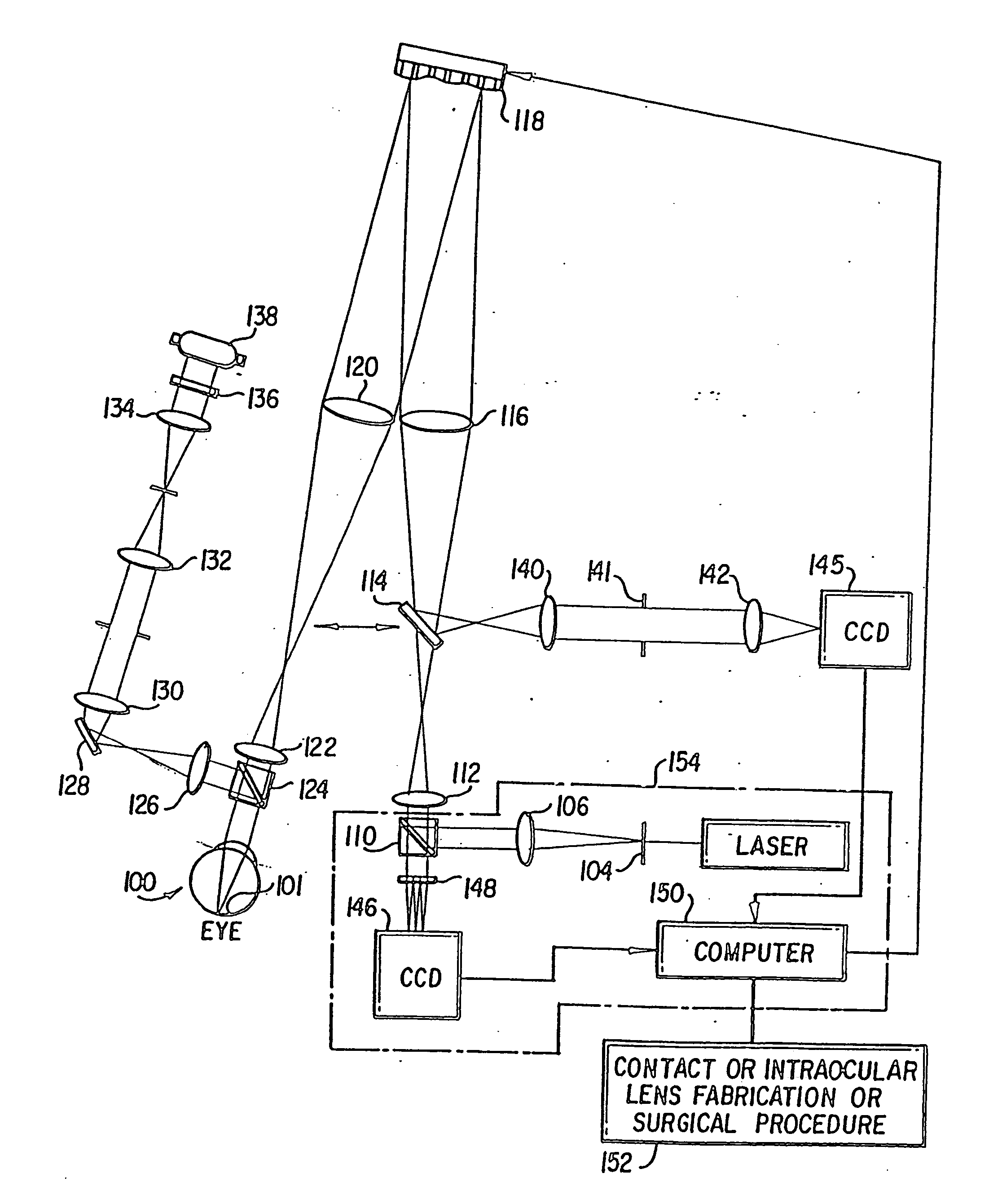
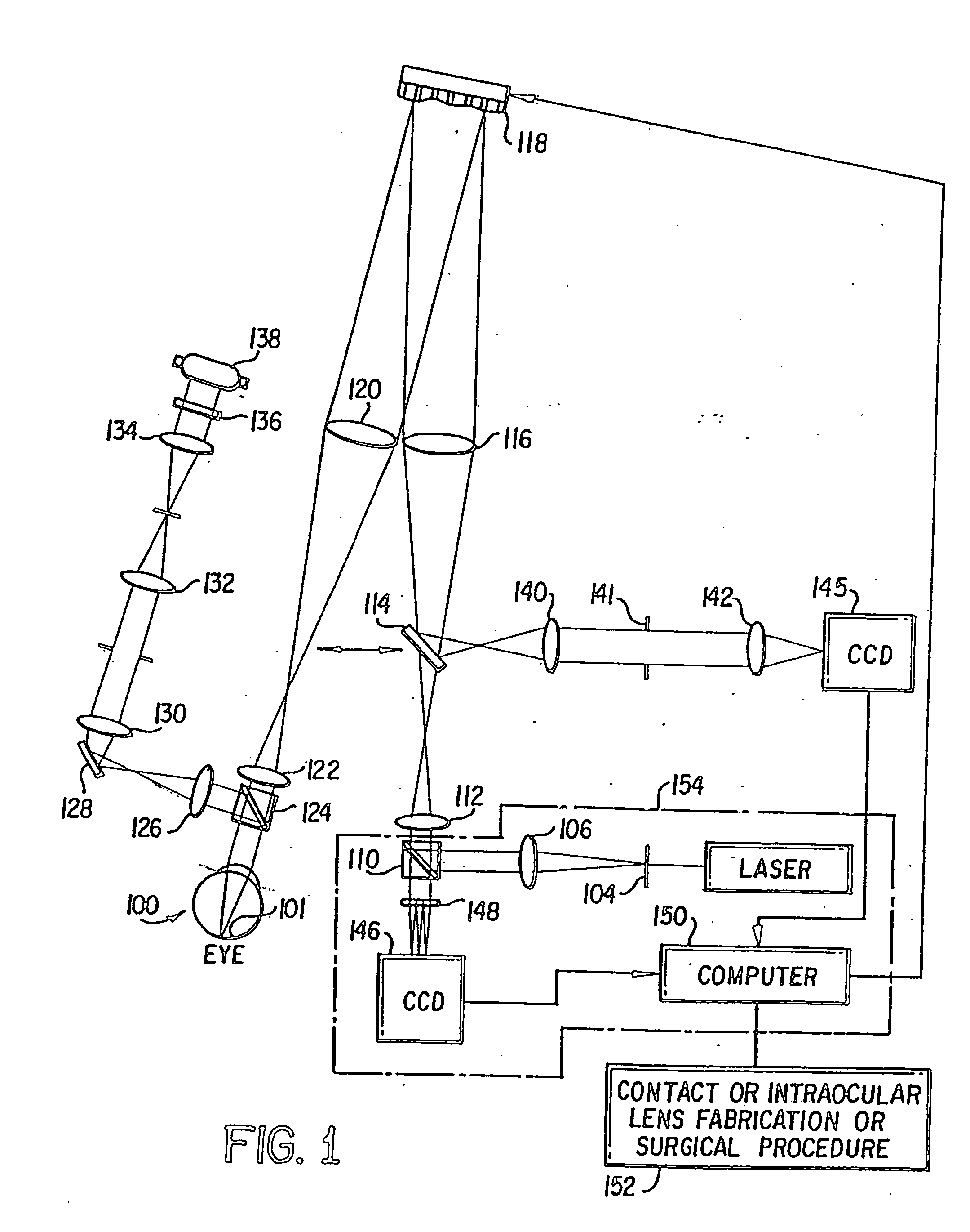
[0023] Referring now to FIG. 1, there is shown, in schematic diagram form, the apparatus of the present invention which can be used to both improve visual performance and to provide high resolution retinal images of eyes. The apparatus of the present invention, as shown in FIG. 1, measures the aberrations of the eye using a Hartmann-Shack wavefront sensor and then corrects them in a closed feedback loop with a compensating optical component such as a deformable mirror.
[0024] To measure the eye's wave aberration, a point source is produced on the retina by a laser 102. The light from the laser 102, is controlled by a shutter (not shown). The laser light passes through a spatial filter 104 and is collimated by an achromatic doublet lens 106. The collimated laser beam is reflected by the polarizing beamsplitter 110, passes through the lenses 112 and 116, and is incident onto a deformable mirror 118. The laser beam reflected from the deformable mirror 118 is focused by the lens 120, pa...
PUM
Abstract
A method of and apparatus for improving vision and the resolution of retinal images is described in which a point source produced on the retina of a living eye by a laser beam is reflected from the retina and received at a lenslet array of a Hartmann-Shack wavefront sensor such that each of the lenslets in the lenslet array forms an aerial image of the retinal point source on a CCD camera located adjacent to the lenslet array. The output signal from the CCD camera is acquired by a computer which processes the signal and produces a correction signal which may be used to control a compensating optical or wavefront compensation device such as a deformable mirror. It may also be used to fabricate a contact lens or intraocular lens, or to guide a surgical procedure to correct the aberrations of the eye. Any of these methods could correct aberrations beyond defocus and astigmatism, allowing improved vision and improved imaging of the inside of the eye.
Description
REFERENCE TO RELATED APPLICATION [0001] The present application is a continuation of U.S. patent application Ser. No. 10 / 078,163 filed Feb. 20, 2002, now pending, which is a continuation of U.S. patent application Ser. No. 09 / 628,690, filed Jul. 28, 2000, now U.S. Pat. No. 6,379,005, which is a continuation of U.S. patent application Ser. No. 09 / 346,309, filed Jul. 2, 1999, now U.S. Pat. No. 6,095,651, which is a continuation of U.S. patent application Ser. No. 09 / 071,794, filed May 4, 1998, now U.S. Pat. No. 5,949,521, which is a continuation of U.S. patent application Ser. No. 08 / 772,977, filed Dec. 23, 1996, now U.S. Pat. No. 5,777,719. The disclosure of all of the above applications are hereby incorporated by reference in their entireties.BACKGROUND OF THE INVENTION [0002] The present invention is directed to a method of and an apparatus for improving vision and the resolution of retinal images. More particularly, the present invention is directed to a method of and an apparatus...
Claims
Application Information
Patent Timeline
Application Date:The date an application was filed.
Publication Date:The date a patent or application was officially published.
First Publication Date:The earliest publication date of a patent with the same application number.
Issue Date:Publication date of the patent grant document.
PCT Entry Date:The Entry date of PCT National Phase.
Estimated Expiry Date:The statutory expiry date of a patent right according to the Patent Law, and it is the longest term of protection that the patent right can achieve without the termination of the patent right due to other reasons(Term extension factor has been taken into account ).
Invalid Date:Actual expiry date is based on effective date or publication date of legal transaction data of invalid patent.
Patent Type & AuthorityApplications(United States)

