
Intraocular implant devices

a technology of implanted ocular parts and implants, which is applied in the field of intraocular lens shaping devices, can solve the problems of biocompatibility of nickel titanium alloys and other biocompatible materials, and achieve the effect of simplifying lens exchang

Inactive Publication Date: 2011-11-01
ALCON INC
View PDF261 Cites 127 Cited by
  • Summary
  • Abstract
  • Description
  • Claims
  • Application Information

AI Technical Summary

Benefits of technology

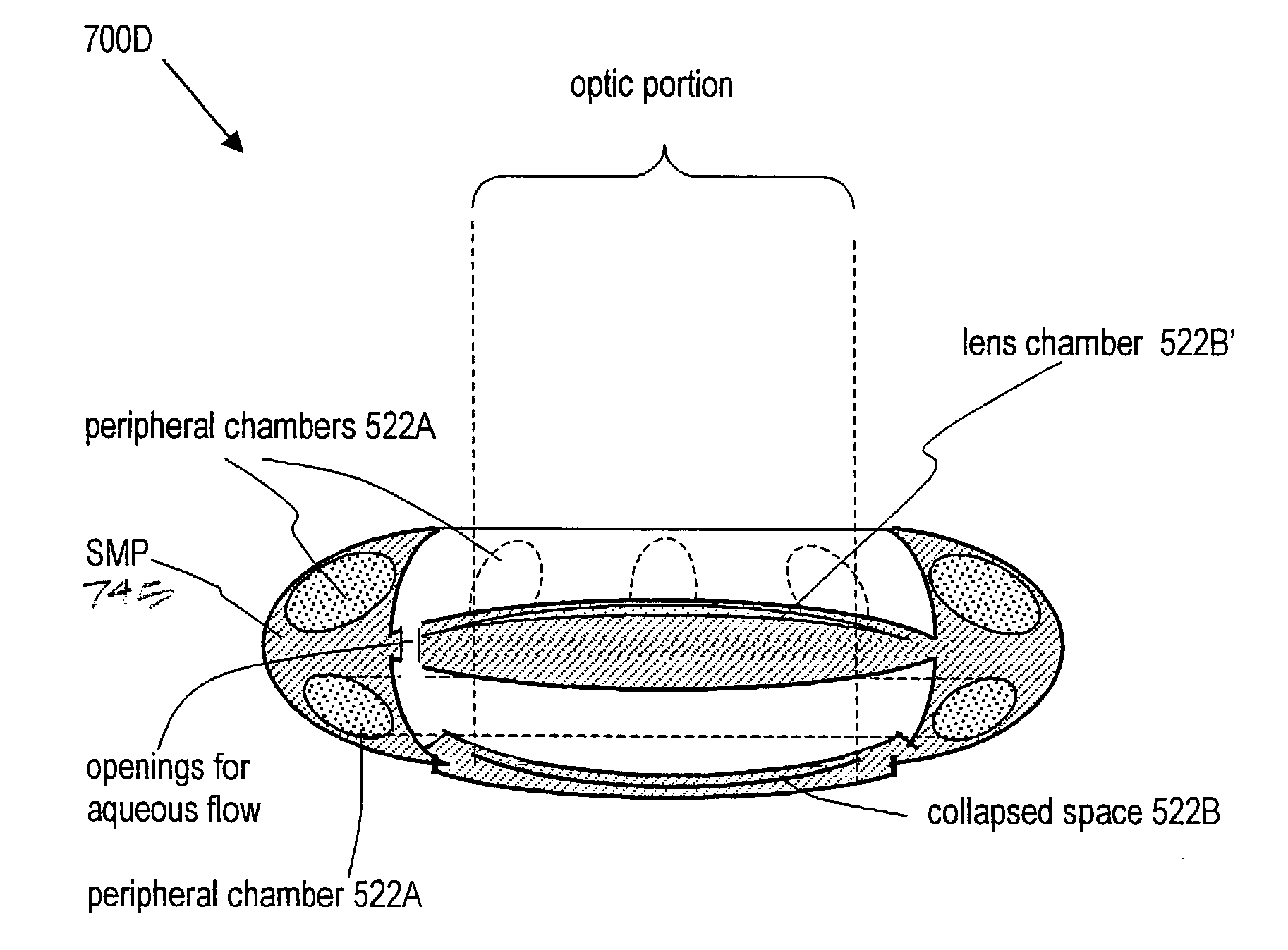
[0018]Accordingly, a principal advantage of the present invention is the provision of deformable, rollable intraocular devices such as capsular shaping devices that utilize shape memory alloy forms, such shaping devices enabling an artificial lens system to provide accommodative amplitude (diopters of power modification).
[0019]The invention advantageously provides a capsular shaping element with integrated optics that require only a very small entry incision for implantation—for example a sub-1 mm. minimal incision through the cornea.
[0020]The invention advantageously provides an independent module comprising a capsular shaping structure of a thin film material that conforms to and maintains an intracapsular volume for receiving an IOL.
[0021]The invention provides a capsular shaping structure of a superelastic shape memory alloy form within a a shape memory polymer envelope that conforms to and maintains an intracapsular volume.
[0022]The invention advantageously provides an independent module comprising a capsular shaping structure that can cooperate with drop-in fixed focus IOL or a drop-in accommodating IOL.
[0023]The invention advantageously provides an independent module comprising a capsular shaping element that allows for simplified lens exchange.

Problems solved by technology

Nickel titanium alloys are also known to be biocompatible.

Method used


Image

  • Intraocular implant devices
  • Intraocular implant devices
  • Intraocular implant devices

Examples


Embodiment Construction

I. Principles of Superelasticity and Shape Memory in Classes of Ophthalmic Implant Materials

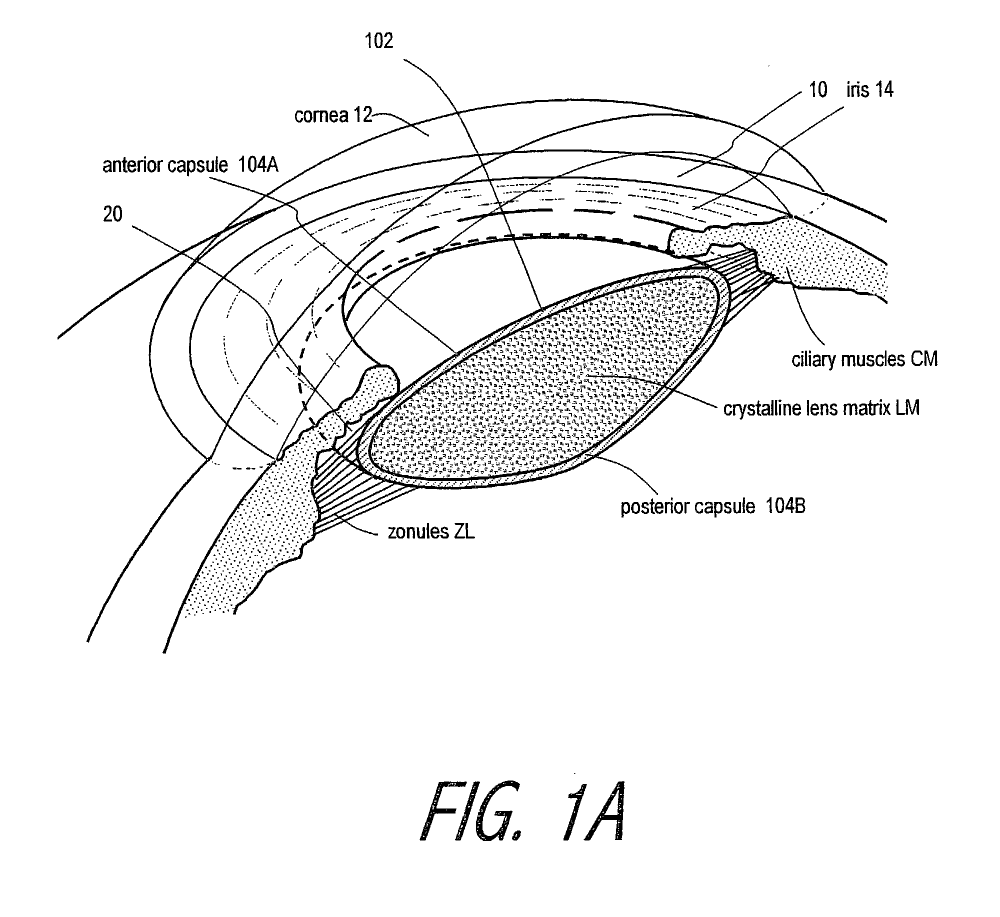
[0065]The capsular shaping element (CSE) of the invention is adapted for providing a biomimetic lens capsule complex that will enable an accommodative lens system, which can have several variants. The term biomimetic lens capsule is derived from the word biomimesis, which defines the development of structures that mimic life, or that imitate biological systems. In this case, the objective is to develop an implant that mimics the inherent elasticity of a young lens capsule for cooperating with the ciliary muscle to alter the shape or translation of an implanted optic element.

[0066]The biomimetic lens capsules corresponding to the invention are enabled by the phenomena of shape memory and superelasticity that are unique to certain newly developed so-called intelligent materials. In particular, one embodiment of CSE comprises a thin-film expanse of a nickel titanium alloy that is fabricated in a...


PUM


Abstract

A deformable intracapsular implant device for shaping an enucleated lens capsule sac for use in cataract procedures and refractive lensectomy procedures. In one embodiment, the intraocular implant devices rely on thin film shape memory alloys and combine with the post-phaco capsular sac to provide a biomimetic complex that can mimic the energy-absorbing and energy-releasing characteristics of a young accommodative lens capsule. In another embodiment, the capsular shaping body is combined with an adaptive optic. The peripheral capsular shaping body carries at least one fluid-filled interior chamber that communicates with a space in a adaptive optic portion that has a deformable lens surface. The flexing of the peripheral shaping body in response to zonular tensioning and de-tensioning provides an inventive adaptive optics mechanism wherein fluid media flows between the respective chambers “adapts” the optic to increase and decrease the power thereof. In one embodiment, the capsular shaping body carries a posterior negative power adaptive optic that can be altered in power during accommodation to cooperate with an independent drop-in exchangeable intraocular lens.

Description

CROSS-REFERENCE TO RELATED APPLICATIONS[0001]This application claims benefit under 35 U.S.C. §119(e) of Provisional U.S. Patent Application Ser. No. 60 / 353,847 filed Feb. 2, 2002 titled Intraocular Lens and Method of Making. This application also claims benefit of the following other Provisional U.S. Patent Applications: Ser. No. 60 / 362,303 filed Mar. 6, 2002 titled Intraocular Lens and Method of Making; Ser. No. 60 / 378,600 filed May 7, 2002 titled Intraocular Devices and Methods of Making; Ser. No. 60 / 405,471 filed Aug. 23, 2002 titled Intraocular Implant Devices and Methods of Making, Ser. No. 60 / 408,019 filed Sep. 3, 2002 titled Intraocular Lens and Ser No. 60 / 431,110 filed Dec. 4, 2002 titled Intraocular Implant Devices and Methods of Making. All of the above applications are incorporated herein in their entirety by this reference.BACKGROUND OF THE INVENTION[0002]1. Field of the Invention[0003]The present invention is directed to intraocular implant devices and more specifically...

Claims


Application Information

Patent Timeline
Patent Type & Authority Patents(United States)
IPC IPC(8): A61F2/16
CPCA61F2/1648A61F2/1694A61F2/1635A61F2/1624A61F2210/0014A61F2/1601A61F2250/0003A61F2310/00023A61F2002/1682A61F2002/16901
Inventor SHADDUCK, JOHN H.
Owner ALCON INC
Learn More