Pressure activated latch

a technology of latches and latches, applied in the field of pressure activated latches, can solve the problems of not providing for the valve to remain closed, the pilot's manual operation, and the door unlocking and inflating of inflatable bags, so as to prevent fluid communication

Active Publication Date: 2007-08-30
APICAL INDS
View PDF12 Cites 18 Cited by
  • Summary
  • Abstract
  • Description
  • Claims
  • Application Information

AI Technical Summary

Benefits of technology

[0010] The latch is configured so that when a pressurized fluid is injected into the fluid inlet it causes the latch pin to slide within housing thereby sequentially unlocking the emergency door and inflating the inflatable device. After the inflatable device is infl

Problems solved by technology

A first disadvantage of the system is that it does not provide for a valve that remains closed until a predetermined pressure is applied.
As a result, any increase in pressure may cause the doors to unlock and the inflatable bags to inflate even when undesired.
Another disadvantage is that it requires manual operation by the pilot even after the initial activation of the system.
A first disadvantage o

Method used


Image

  • Pressure activated latch
  • Pressure activated latch
  • Pressure activated latch

Examples


Embodiment Construction

[0022] In the following paragraphs, the present invention will be described in detail by way of example with reference to the attached drawings. Throughout this description, the preferred embodiment and examples shown should be considered as exemplars, rather than as limitations on the present invention. As used herein, the “present invention” refers to any one of the embodiments of the invention described herein, and any equivalents. Furthermore, reference to various feature(s) of the “present invention” throughout this document does not mean that all claimed embodiments or methods must include the referenced feature(s).

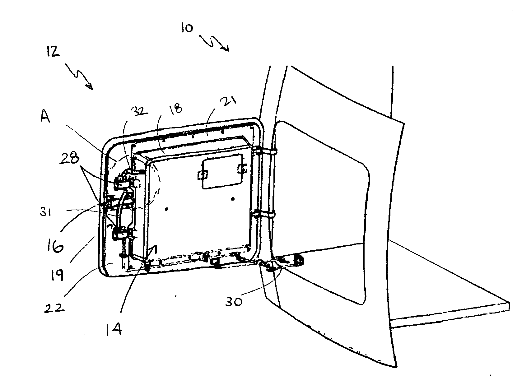
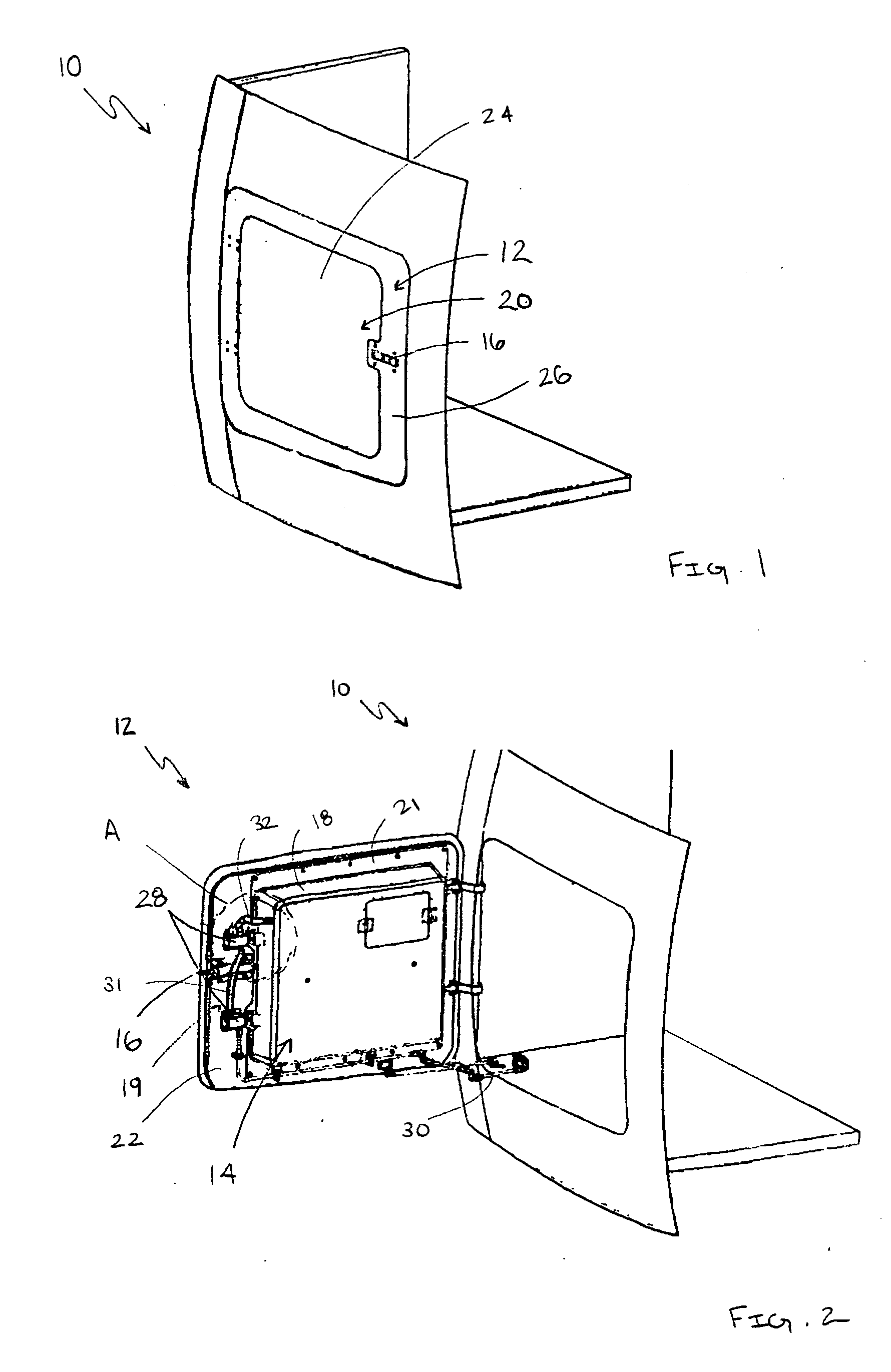
[0023] Referring to FIGS. 1, a panel 10 on the fuselage of an aircraft, such as a helicopter, includes a baggage compartment door 12 that provides access to a baggage compartment. An emergency life raft kit 14 is incorporated into baggage compartment door 12. Life raft kit 14 (not shown in FIG. 1) is located in door 12 because it is easily accessible for installati...


PUM


Abstract

A pressure activated latch includes a latch housing, a fluid inlet, a fluid outlet, an internal biasing member and a sliding latch pin that is configured to engage a latch tab that is substantially adjacent to the latch housing. The latch pin is slidable between a first position in which the latch pin prevents fluid communication between the fluid inlet and the fluid outlet and engages the latch tab and a second position in which the latch pin is disengaged from the latch tab and fluid communication is permitted between the fluid inlet and the fluid outlet. The internal biasing member is configured to apply a force upon the latch pin to bias it into the first position.

Description

FIELD OF THE INVENTION [0001] The present invention is directed to a pressure activated latch, and more particularly to a pressure activated latch for an emergency life raft on an aircraft. BACKGROUND OF THE INVENTION [0002] Emergency flotation devices are required on many aircraft to provide emergency assistance to passengers in the event the aircraft experiences an emergency situation and is forced down in water. Emergency flotation devices generally include systems designed to float the aircraft, systems for emergency life rafts and life vests for individual occupants. [0003] One example of an airplane flotation system is shown in U.S. Pat. No. 1,776,865. The system includes inflatable bags located in a forward portion of an airplane and is manually operated by a pilot. The bags are stored in a non-inflated state within closed compartments. The system utilizes pressure cylinders to sequentially unlock doors of the compartments and inflate the inflatable bags. During operation the...

Claims


Application Information

Patent Timeline
IPC IPC(8): B63B35/58
CPCB64C1/1415E05B51/02E05B47/0038Y10T292/0969Y10T292/097Y10T292/1021
Inventor BERMAL, JAY VELITARIO
Owner APICAL INDS
Why Eureka
Try Eureka