Endovascular filter

Inactive Publication Date: 2007-08-30
COOK INC +2
View PDF99 Cites 16 Cited by
  • Summary
  • Abstract
  • Description
  • Claims
  • Application Information

AI Technical Summary

Benefits of technology

[0009] The foregoing problem is solved and a technical advance is achieved in an illustrative endovascular filter for retrievable deployment in a blood vessel of a patient. A plurality of struts extend and diverge from an apical hub at a proximal end to respective distal ends adapted to anchor to the vessel wall when expanded and deployment at a treatment site in a blood vessel of a patient, and lengths of the distal ends of the struts are engageable with and against the vessel wall when deployed. The distal end lengths, and preferably the anchoring sections also, are coated with an antiproliferative agent or bioactive material that prevents or minimizes tissue growth. One such particularly useful bioactive material is pacl

Problems solved by technology

Such clot becomes a serious risk of pulmonary embolism if it breaks loose.
Normally, removal of a filter is only advisable within a couple of weeks after implantation due to intimal

Method used


Image

  • Endovascular filter
  • Endovascular filter
  • Endovascular filter

Examples


Embodiment Construction

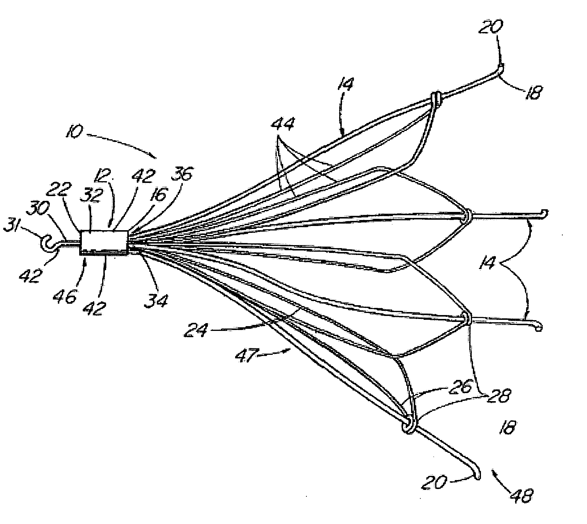
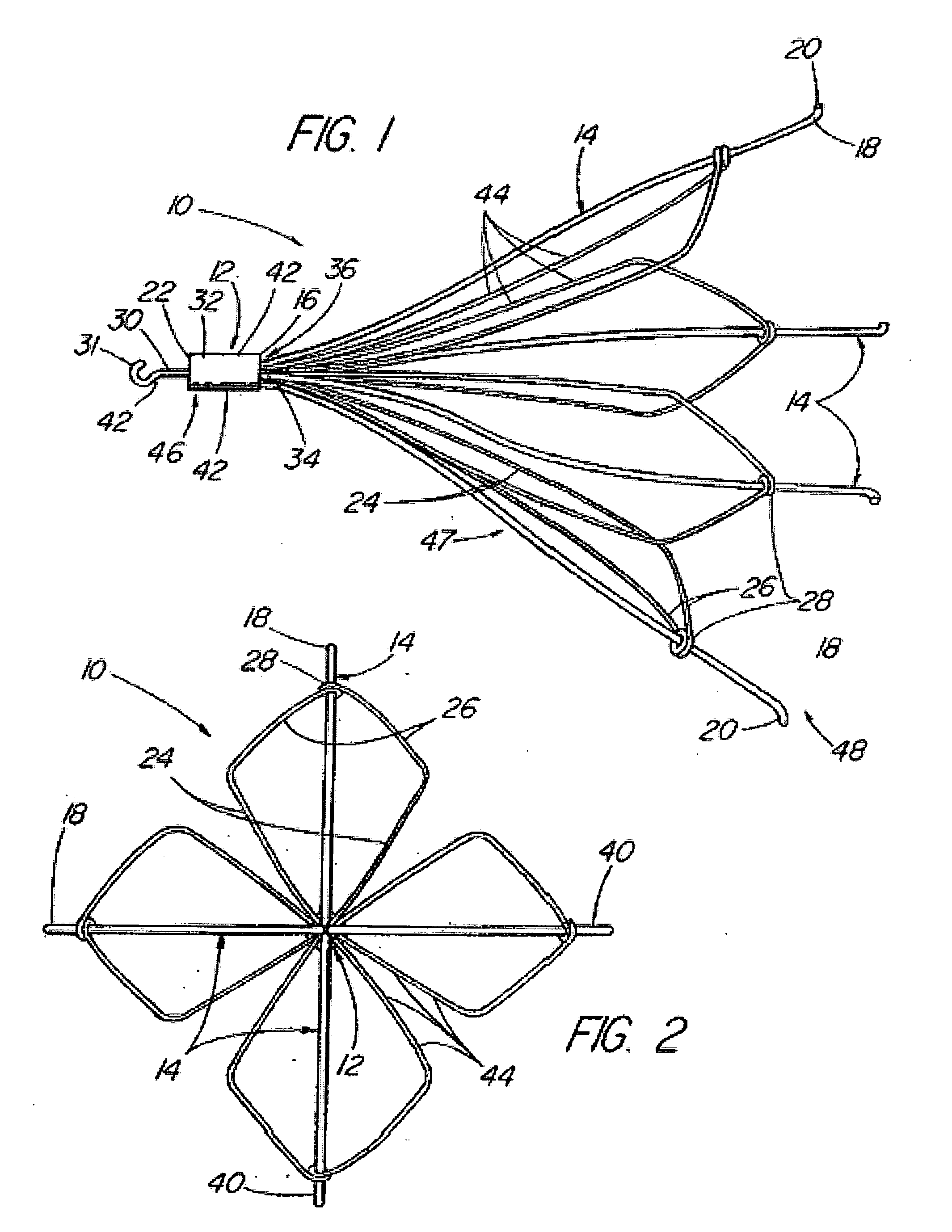
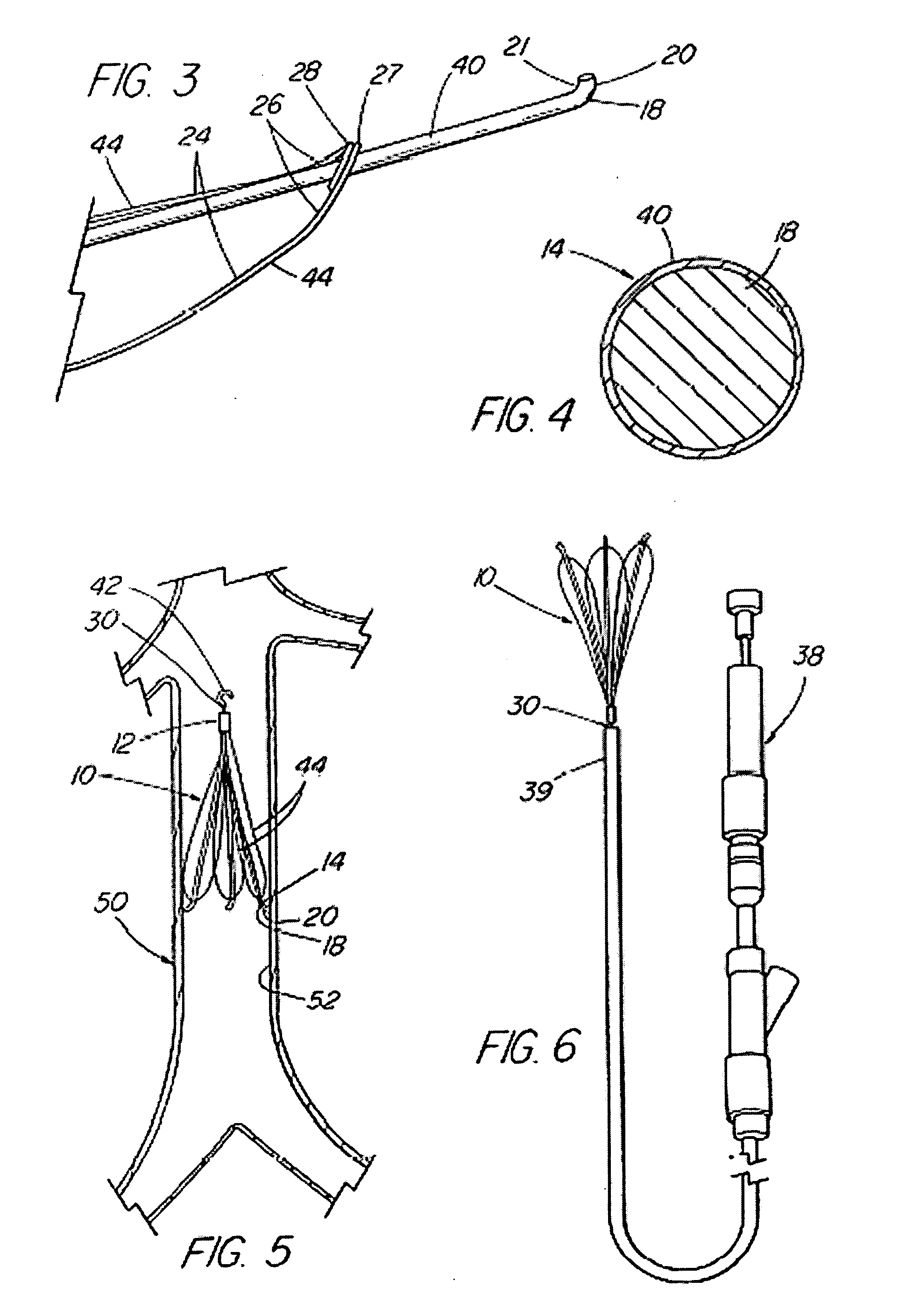
[0021] Vena cava filter 10 is shown in FIGS. 1 to 3 in its fully expanded condition to have a proximal portion 46, a medial portion 47 and a distal portion 48. An apical hub body 12, in the proximal portion 46 of the filter 10, has a first or distal end 16 and a second or proximal end 22. A plurality of struts 14 have proximal ends 34 that are secured to the distal end 16 of hub body 12 and have distal end portions 18 that have anchoring sections 20. The struts 14 divergingly extend distally from the distal end 16 of hub body 12. The second or proximal end 22 of hub body 12 has a retrieval section 30 extending therefrom that terminates in a hook 31. The specific embodiment of the filter 10 that is illustrated is shown to have pairs of side elements 24 having proximal ends 36 that are connected to the first end 16 of the hub body 12, each pair of which is associated with a strut 14. The side elements 24 also extend distally in diverging pairs from first end 16 of the hub body 12 and ...


PUM


Abstract

Endovascular filter (10) including a plurality of struts (14) with distal ends (18) adapted to anchor the filter to the vessel wall after deployment, such as by having barbs (20), the filter being adapted to be retrieved if desired. Strut distal ends (18) are coated with an antiproliferative agent (40) that inhibits the ingrowth of tissue around the filter, thereby permitting the filter to be retrieved and removed atraumatically after a prolonged period of time, thus extending the useful life of the retrievable filter. Optionally, the proximal end (22) of the filter may also be so coated, or the entire filter.

Description

CROSS-REFERENCE TO RELATED APPLICATIONS [0001] This application is a continuation-in-part application of: (1) co-pending U.S. patent application Ser. No. 10 / 172,725, filed Jun. 14, 2002, which claims priority to provisional application Ser. No. 60 / 298,803; and (2) co-pending U.S. patent application Ser. No. 10 / 223,415, filed Aug. 19, 2002, which is a continuation-in-part of application of co-pending non-provisional application Ser. No. 09 / 027,054, filed Feb. 20, 1998, which claimed priority to provisional application Ser. No. 60 / 038,459, filed Feb. 20, 1997, and which was also a continuation-in-part application of and claimed priority to application Ser. No. 08 / 645,646, filed May 16, 1996, now U.S. Pat. No. 6,096,070, issued Aug. 1, 2000, which was in turn a continuation-in-part application of and claimed priority to application Ser. No. 08 / 484,532, filed Jun. 7, 1995, now U.S. Pat. No. 5,609,629, issued Mar. 11, 1997. All of the above-referenced patent applications are incorporated...

Claims


Application Information

Patent Timeline
IPC IPC(8): A61M29/00
CPCA61F2/01A61F2250/0067A61F2230/0086A61F2230/005A61F2002/016A61F2/0105
Inventor GRIFFIN, DENNISMOLGAARD-NIELSEN, ARNERAGHEB, ANTHONY O.LEONARD, RAYMOND B. IIFEARNOT, NEAL E.VOORHEES, WILLIAM D. IIIKOZMA, THOMAS G.BATES, BRIAN L.OSBORNE, THOMAS A.
Owner COOK INC
Why Eureka
Try Eureka