
Air conditioning system operating on vehicle waste energy

a technology of air conditioning system and vehicle waste energy, which is applied in the direction of reciprocating combination engines, applications, lighting and heating apparatus, etc., can solve the problems of reducing the overall vehicle fuel efficiency (e.g., mpg/kpl) by 25 percent or more, increasing the load on the engine, and reducing the overall vehicle fuel efficiency. , the effect of reducing the load

Inactive Publication Date: 2007-09-06
HARRISON THOMAS D
View PDF21 Cites 21 Cited by
  • Summary
  • Abstract
  • Description
  • Claims
  • Application Information

AI Technical Summary

Benefits of technology

This approach reduces fuel consumption and environmental impact by efficiently using waste energy to compress refrigerant, allowing the air conditioning system to operate with minimal engine load, thereby enhancing fuel efficiency and reducing costs.

Problems solved by technology

Although this added load on the engine may appear to be comparatively low, each added load on the power source / engine results in a need to consume additional fuel.
In some situations, for example, operation of the compressor can reduce overall vehicle fuel efficiency (e.g., mpg / kpl) by as much as 25 percent or more.
This simply means that a vehicle will typically consume more fuel during warmer periods (e.g., when using the air conditioner), which of course adds financial costs of additional fuel purchases.
This also means that operating an air conditioner can ultimately result in additional fossil fuel exhaust expelled into the environment.
The additional costs associated with the larger battery, the complex mechanisms used by the hybrid vehicle to capture waste energy, and the extra weight added thereby, however, tend to make conventional hybrid vehicles fairly expensive.
These complex mechanisms also tend to be expensive to maintain over time, and such costs could tend to offset some of the savings associated with the added fuel economy.

Method used


Image

  • Air conditioning system operating on vehicle waste energy
  • Air conditioning system operating on vehicle waste energy
  • Air conditioning system operating on vehicle waste energy

Examples


Embodiment Construction

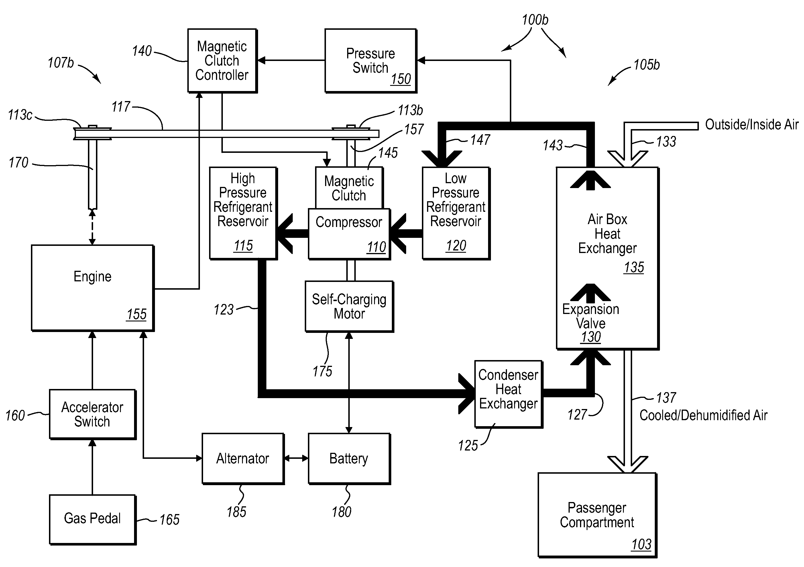
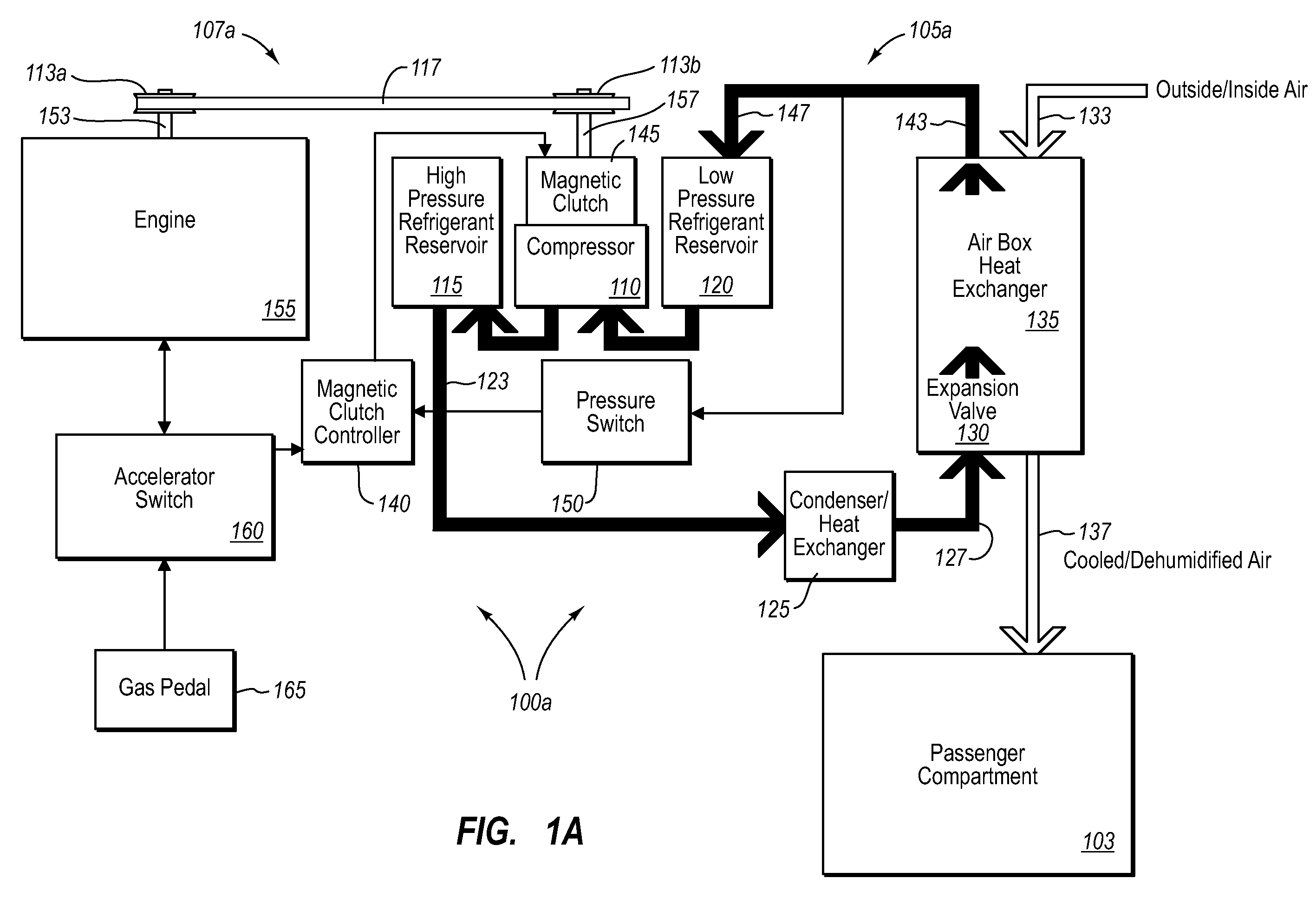
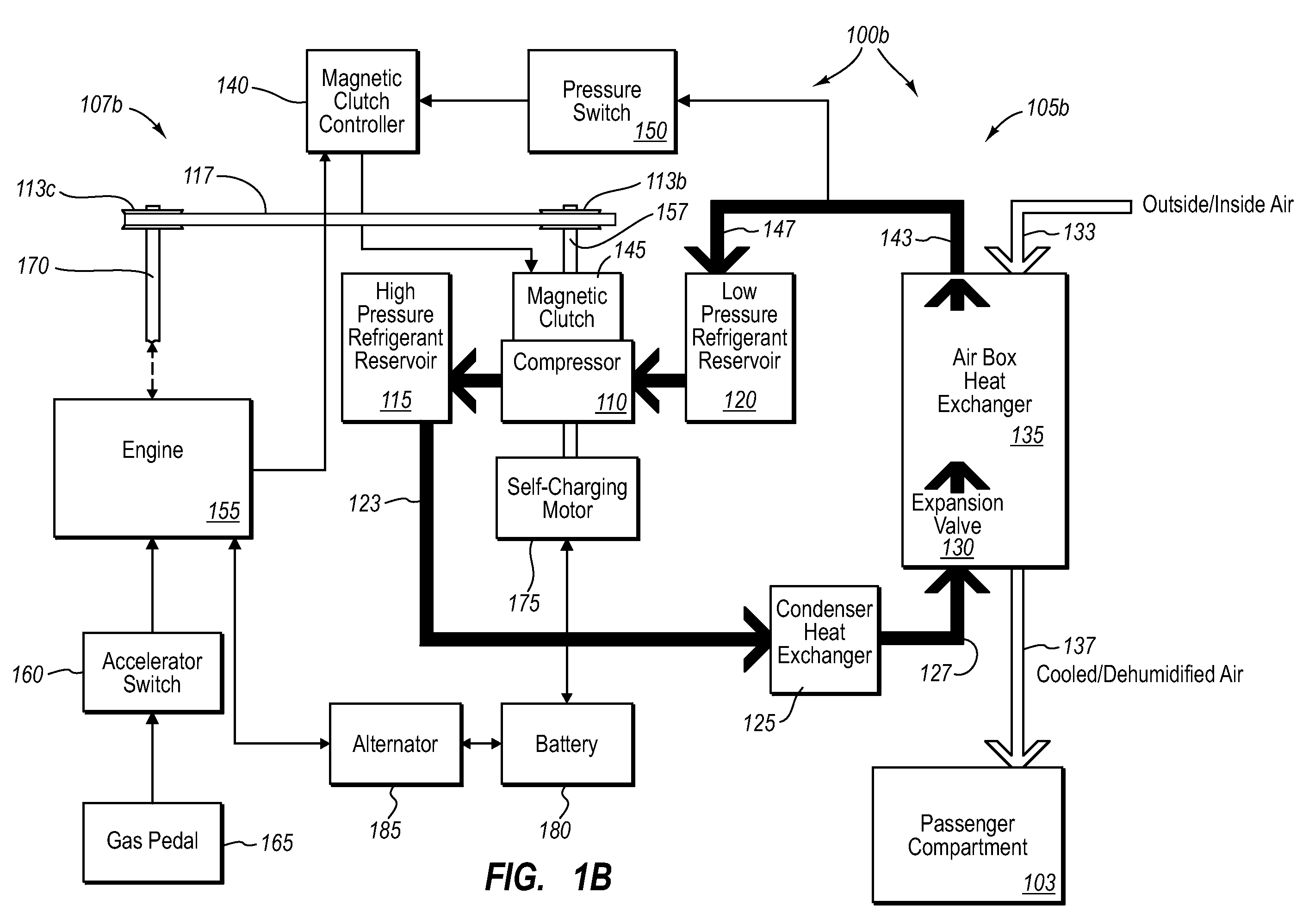
[0026]Implementations of the present invention extend to systems, apparatus, and methods configured to mitigate fuel economy issues associated with using air conditioning systems in conventional vehicles. In particular, implementations of the present invention include readily-addable, low-cost components configured to coincide or constrain compressor (e.g., of air conditioning systems) operations principally with the presence of passive energy sources (i.e., vehicle waste mechanical kinetic energy—“waste energy”), and independent of braking actions. In one implementation, an air conditioning system can also be configured to use multiple sources of passive energy (i.e., “dual source” operations). As such, a vehicle air conditioning system can be easily and inexpensively configured to minimize loads on active energy sources (e.g., the engine) during air conditioner operation.

[0027]As will be appreciated more fully herein, the principles described herein can be performed with a number ...


PUM


Abstract

A waste energy-based vehicle air conditioning system includes efficient compression driving means coupled to refrigeration means. In one implementation, the compression driving means includes a controller (e.g., magnetic clutch) that couples mechanical waste energy from an engine fan axle, a vehicle drive shaft, or a transmission shaft to an axle of a refrigerant compressor. Alternatively, the controller can also include a battery that is charged from the mechanical waste energy. Upon detecting certain pressure values, the controller powers the refrigerant compressor with a rotating axle (e.g., during deceleration) or with battery power, as appropriate. In one implementation, the controller is configured to engage compression immediately upon detecting that the vehicle is decelerating. One or more kits can be used to retrofit existing vehicles to operate the respective air conditioning systems principally on waste energy.

Description

CROSS-REFERENCE TO RELATED APPLICATIONS[0001]The present invention claims the benefit of priority to U.S. Provisional Patent Application No. 60 / 813,611, filed on Mar. 2, 2006, entitled “Air Conditioning System,” the entire contents of which are incorporated by reference herein.BACKGROUND OF THE INVENTION[0002]1. The Field of the Invention[0003]Implementations of the present invention relate in part to air conditioning systems, such as used in automobiles.[0004]2. Background and Relevant Art[0005]For the past several decades, air conditioning systems have been used in automobiles and other motor vehicles during hot weather to provide more comfortable conditions for drivers and other vehicle occupants. Typically, an air conditioning system uses a refrigerant, which it compresses and expands at various points to cool warm air.[0006]In general, vehicular air conditioning systems use energy from an active power source, such as an operating vehicle engine, to compress air conditioner refr...

Claims


Application Information

Patent Timeline
Patent Type & Authority Applications(United States)
IPC IPC(8): F25B49/00F25B27/00B60H1/32
CPCB60H1/3208B60H1/3222B60H2001/327B60H2001/3266B60H2001/3248
Inventor HARRISON, THOMAS D.
Owner HARRISON THOMAS D
Learn More