
Dual Rotor Type Motor

Active Publication Date: 2007-09-06
LG ELECTRONICS INC
View PDF9 Cites 46 Cited by
  • Summary
  • Abstract
  • Description
  • Claims
  • Application Information

AI Technical Summary

Benefits of technology

[0019] A dual rotor type motor according to the present invention has an advantageous effect that the output of the motor may be enhanced without enlarging the size and weight of the motor, because the inner rotor and the outer rotor are provided in the inner portion and outer portion of the stator according to the present invention.
[0020] Furthermore, according to the present invention it is easy to secure the stator to an appliance such as a washing machine, because the core of the stator and the insulator are supported by the molding part.
[0021] Still further, in case that the molding part is surrounding the core of the stator, the insulator and the coil, water-proof efficiency of the stator may be enhanced. Thus, when applied to the appliances such as a washing machine using water, there is little short circuit caused by water on the stator and durability of the stator also may be enhanced.
[0022] Still further, in case the plurality of the cooling hole parts is formed, air for cooling is ventilated smoothly to radiate the heat of the motor more efficiently even in rotating / reverse-rotating the shaft of the motor by agitating.
[0023] Still further, according to the present invention the inner space of the inner rotor may be cooled efficiently, because air can flow into the inner and outer side of the inner rotor through the intervals on the portion having the outer rotor and the inner rotor fastened thereto by the embossing of the base of the outer rotor.

Problems solved by technology

However, the indirect method has some problems of energy loss and a lot of noise, which are caused in a process transmitting the driving force.
However, the above related art motor has a limitation of increasing output and power, because it uses one rotor.
Thereby, it may cause a problem that size and weight of a motor should be increased.

Method used


Image

  • Dual Rotor Type Motor
  • Dual Rotor Type Motor
  • Dual Rotor Type Motor

Examples


first embodiment

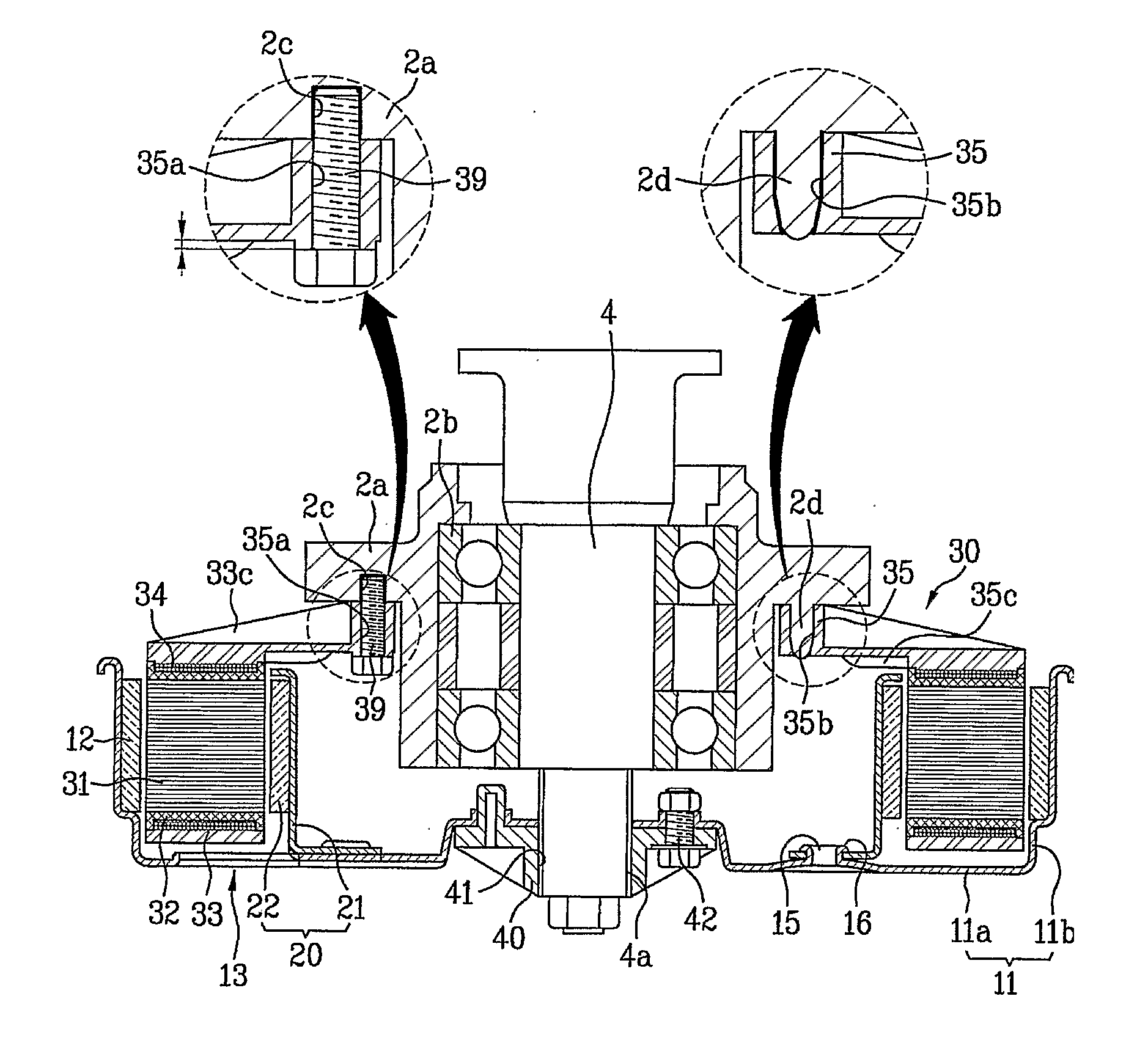
[0044] First, referring to FIGS. 3 through 9, a dual rotor type motor according to the present invention will be described.

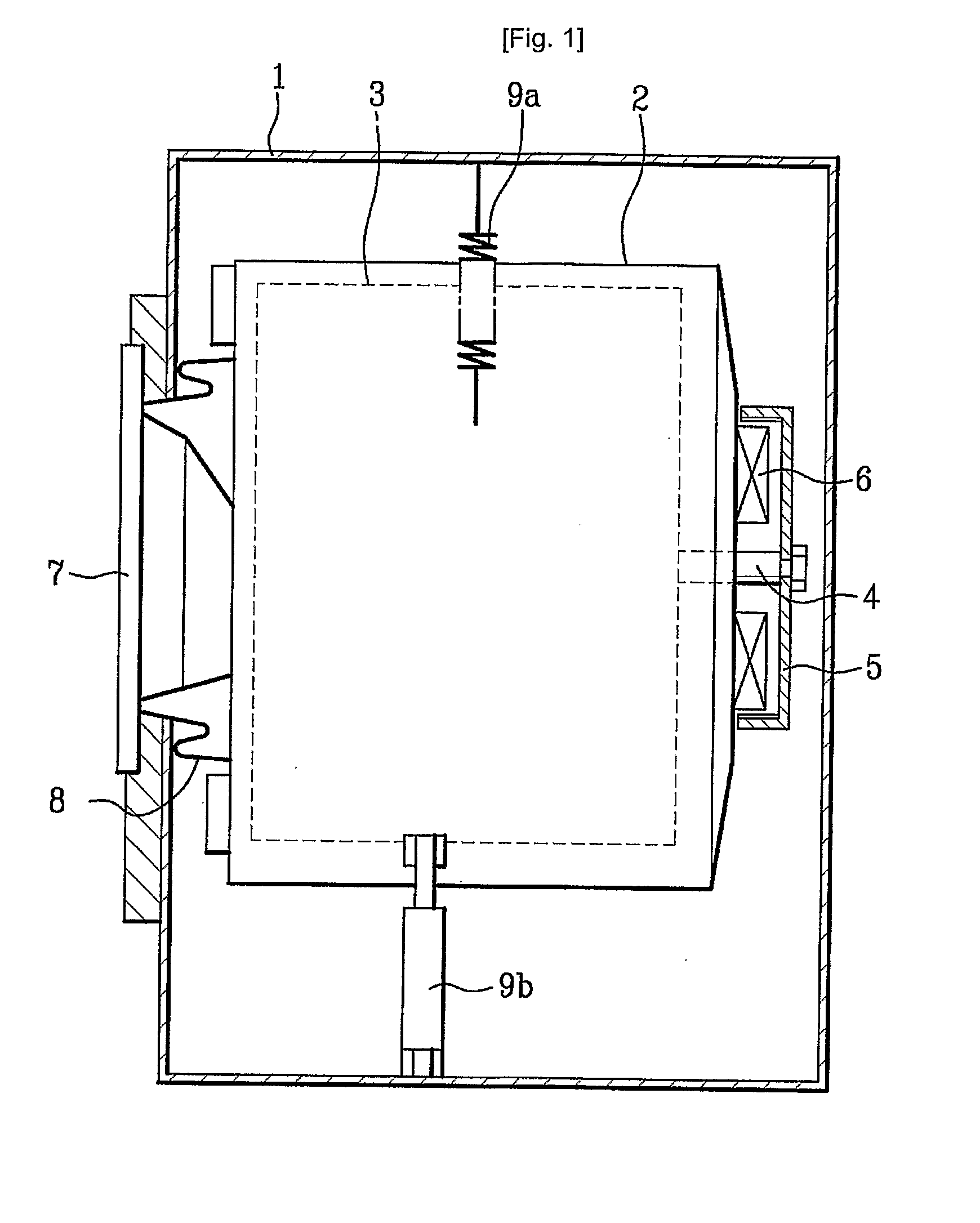
[0045] For understanding, it is embodied that the dual rotor type motor of the present invention is applied to a washing machine. However, the dual rotor type motor of the present invention may be applied not only to a washing machine but also to other appliances such as an air conditioner.

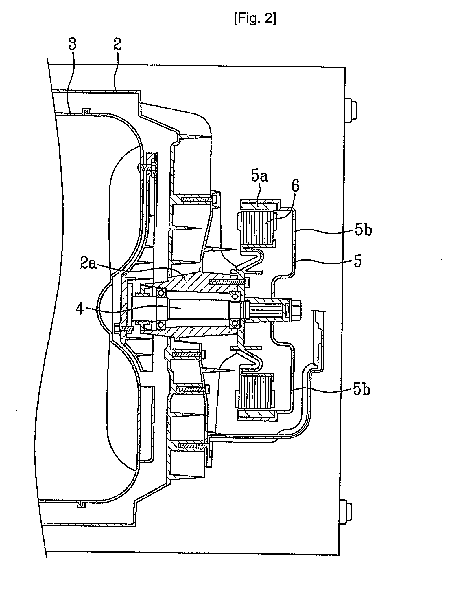
[0046] As shown in FIGS. 3 and 4, a shaft 4 is rotatably mounted on a rear surface center of a tub 2 (see FIG. 1) for driving a drum 3. The shaft 4 is supported by a bearing 2b within a bearing housing 2a provided in rear of the tub 2.

[0047] A motor is mounted on the bearing housing 2a for driving the shaft 4, the motor is provided so as to maintain a predetermined distance between a stator 30 secured on the bearing housing 2a and an inner / outer surface of the stator 30, and there are an outer rotor 10 and an inner rotor 20 having a first / second end of the shaft 4 secured th...

second embodiment

[0089] As shown in FIG. 10 illustrating the stator of the dual rotor type motor, in case that the single-partition core and the insulator are discrete components, the single-partition core is divided into a first single-partition core 131a of a middle portion thereof and a second single-partition core 131b and the insulator 132 is a one body not divided into the lower and upper insulator. Hence, the first and second single-partition core 131a and 131b are inserted through both opened portions of the insulator 132, and then secured by means of caulking.

[0090] The divided surface of the first and second single-partition core 131a and 131b is bended like an L-shape for increasing secured area of the core.

[0091]FIG. 11 illustrates a third embodiment of the stator 30, especially a core and an insulator. According to the third embodiment, the stator 30 includes an outer core 231a having a plurality of teeth 231 extending outwardly in a radial direction and a base 131d connecting each inn...


PUM


Abstract

Abstract: A dual rotor type motor of the present invention is disclosed. The dual rotor type motor according to the present invention includes a shaft rotatably provided in a motor securing part; a rotor assembly rotated with a center thereof fastened to the shaft, the rotor assembly comprising an outer rotor spaced apart at a predetermined distance from the center of the shaft with magnets secured along a circumferential direction, and an inner rotor provided in an inside of the outer rotor at a predetermined distance spaced apart with magnets secured along a circumferential direction; and a stator comprising a core made of metal, an insulator of an insulating material for surrounding the core so as to have a first and second surface of the core facing each other to be exposed outside, a coil wound on the outer surface of the insulator, a molding part of insulating material for surrounding the insulator and the coil by insert molding as one body to expose the first and second surface of the core in a state of the insulator being provided in a circular shape and a fixing part for securing the molding part to the motor securing part, and the stator provided between the outer rotor and the inner rotor for having the exposed first and second surface of the core to face each other at a predetermined distance with the magnet of the outer and inner rotor.

Description

TECHNICAL FIELD [0001] The present invention relates to a motor, and more particularly, to a dual rotor type brushless DC (hereinafter, BLDC) motor which improves torque by means of dually mounting rotors in both sides of a stator of an appliance such as a washing machine. BACKGROUND ART [0002] In general, according to a drum type washing method, detergent, washing water and the laundry are introduced and washing is performed by using a friction power between a rotating drum and the laundry after receiving a drive force of a motor. Thereby, the drum type washing method has not only an enhanced washing efficiency but also little laundry damage and laundry tangle. [0003] According to a driving method of a motor thereof, a conventional drum type washing machine is classified into an indirect drive type in which driving force of a motor is indirectly transmitted to a drum through a belt tied around a motor pulley and a drum pulley, and a direct drive type in which driving force of a mot...

Claims


Application Information

Patent Timeline
IPC IPC(8): H02K16/02H02K1/22H02K16/00
CPCD06F37/304H02K1/148H02K21/12H02K16/02H02K7/14
Inventor CHOI, SOUNG BONGJEONG, SEONG HAIKIM, YEONG SOOCHO, HUNG MYONGAHN, IN GEUN
Owner LG ELECTRONICS INC
Learn More