Antenna apparatus for multiple input multiple output communication

Inactive Publication Date: 2007-09-06
FUJITSU LTD
View PDF11 Cites 9 Cited by
  • Summary
  • Abstract
  • Description
  • Claims
  • Application Information

AI Technical Summary

Benefits of technology

[0013] It is an object of the present invention to provide an antennal apparatus for a MIMO communication which pre

Problems solved by technology

Accordingly, it is desired that human controllable G(θ, θ) is spatially uniform (nondirectional antenna) for improving a received power, however, it is not practicable to construct such an antenna.
As a result, a case occurs that a directivity of an antenna is null in the direction from which radio waves are coming.
However, the above conventional antenna apparatus has the p

Method used


Image

  • Antenna apparatus for multiple input multiple output communication
  • Antenna apparatus for multiple input multiple output communication
  • Antenna apparatus for multiple input multiple output communication

Examples


Embodiment Construction

[0020] Hereinbelow, the most preferred embodiment for implementing the present invention is explained in detail, by referring to the drawings.

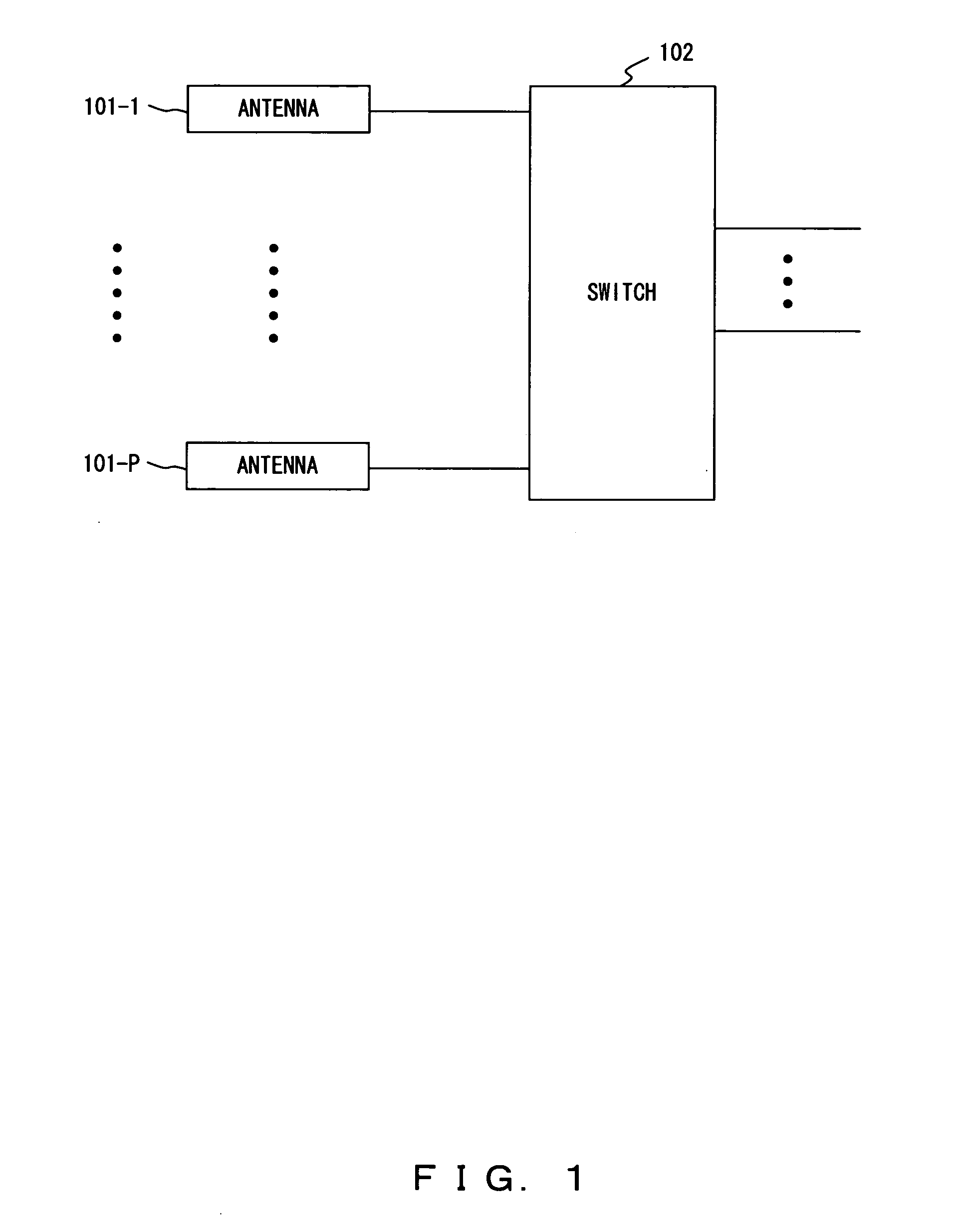
[0021]FIG. 1 shows a principle of an antenna apparatus for a MIMO communication according to the present invention. The antenna apparatus for the MIMO communication comprises P number of antennas 101-1 through 101-P, and a switch 102.

[0022] The antennas 101-1 through 101-P consist of at least two antennas having polarization characteristics or directivities which are different from one another, and are arranged such that the spatial fading correlation is low between each other. The switch 102 selects at least two antennas used for the MIMO communication from the antennas 101-1 through 101-P. Then, the MIMO communication is conducted by using the selected antennas.

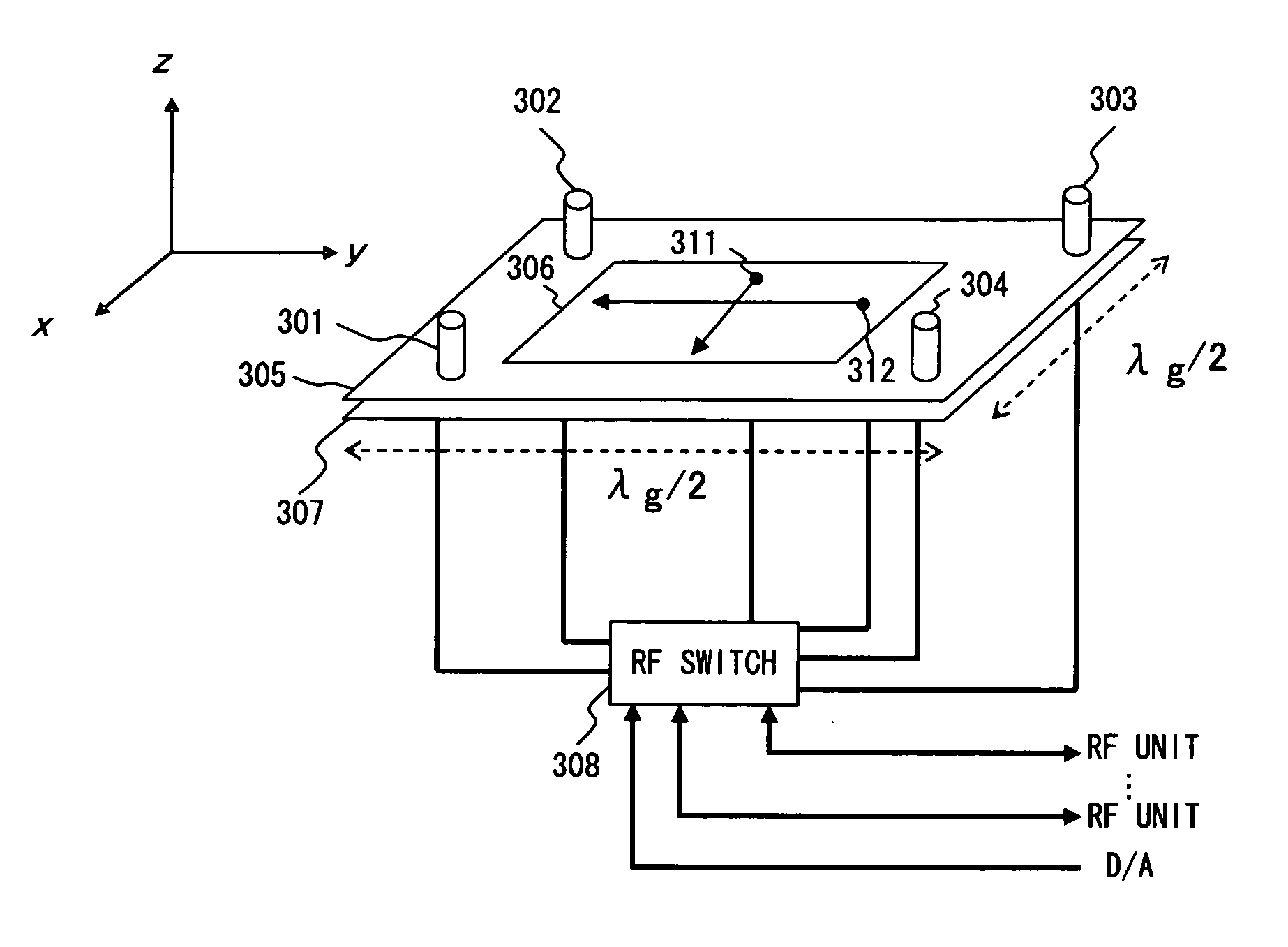
[0023] For example, in the antenna apparatus of FIG. 3 which will be described later, the antennas 101-1 through 101-P correspond to monopole antennas 301 through 304 and a radiati...


PUM


Abstract

At least two antennas are selected from a plurality of antennas which consist of at least two antennas having polarization characteristics or directivities different from one another, and which are arranged such that spatial fading correlations between the antennas are low, and a multiple input multiple output communication is conducted by using the selected antennas.

Description

BACKGROUND OF THE INVENTION [0001] 1. Field of the Invention [0002] The present invention relates to a wireless communication system, and particularly to an antenna apparatus in a MIMO (Multiple Input Multiple Output) system, which conducts wireless communications using a plurality of antennas for transmitting and receiving. [0003] 2. Description of the Related Art [0004] A received signal r in a wireless communication is given as a result of integrating the product of a directivity G(θ, φ) of an antenna and a characteristic H(θ, φ) of a propagation path, as shown in the equation below. r=∫0π∫−ππG(θ,φ)H(θ,φ)dφdθ  (1) [0005] In the above equation, θ and φ respectively represent an azimuth angle and an elevation angle in the receiving side. Generally, because H(θ, φ) is a variable of natural phenomenon which a human can not control, and expresses an incoming wave distribution which is spatially polarized. Accordingly, it is desired that human controllable G(θ, θ) is spatially uniform ...

Claims


Application Information

Patent Timeline
IPC IPC(8): H01Q3/24H04B1/38H04B7/04H04B7/08H04J99/00
CPCH01Q3/24H01Q9/0435H01Q9/30H04B7/0686H01Q21/24H01Q21/28H01Q9/36
Inventor NAKAYA, YUUTAIDA, ICHIROUHONDA, ATSUSHI
Owner FUJITSU LTD
Why Eureka
Try Eureka