
Telephone-receiving call center system

a call center and telephone technology, applied in the field of call center systems, can solve the problems of inability to record essential information correctly, inability to fulfill the call, and inability to make the call

Inactive Publication Date: 2007-09-06
FUJITSU LTD
View PDF2 Cites 22 Cited by
  • Summary
  • Abstract
  • Description
  • Claims
  • Application Information

AI Technical Summary

Benefits of technology

[0012] The above and other objects, features and advantages of the present invention as well as the manner of realizing them will become more apparent whereas the invention itse

Problems solved by technology

However, this conventional call center system has the following problems.
When the operator records essentials of pending information to be transmitted as a response to the previous incoming call on a piece of paper due to a suspension of an operation to create the information in the event of a newly incoming call unanswered because of the fact that all the clients are busy, a customer making the call is inevitably put in a wait state.
In this case, the operator may record the essentials in a hurry and, thus, the essentials are not recorded correctly.
If the incorrect essentials are used later for completing the pending information to be transmitted as a response to the previous incoming call, the completed information is also wrong as well.
If the newly incoming call is put in a wait state, on the other hand, there is raised a problem of a poor service inevitably putting a customer making the newly incoming call in a wait state till completion of an ongoing operation to create information to be transmitted as a response to the previous incoming call and a poor service caused by an inability to give a fast response to a customer making this newly incoming call.

Method used


Image

  • Telephone-receiving call center system
  • Telephone-receiving call center system
  • Telephone-receiving call center system

Examples


Embodiment Construction

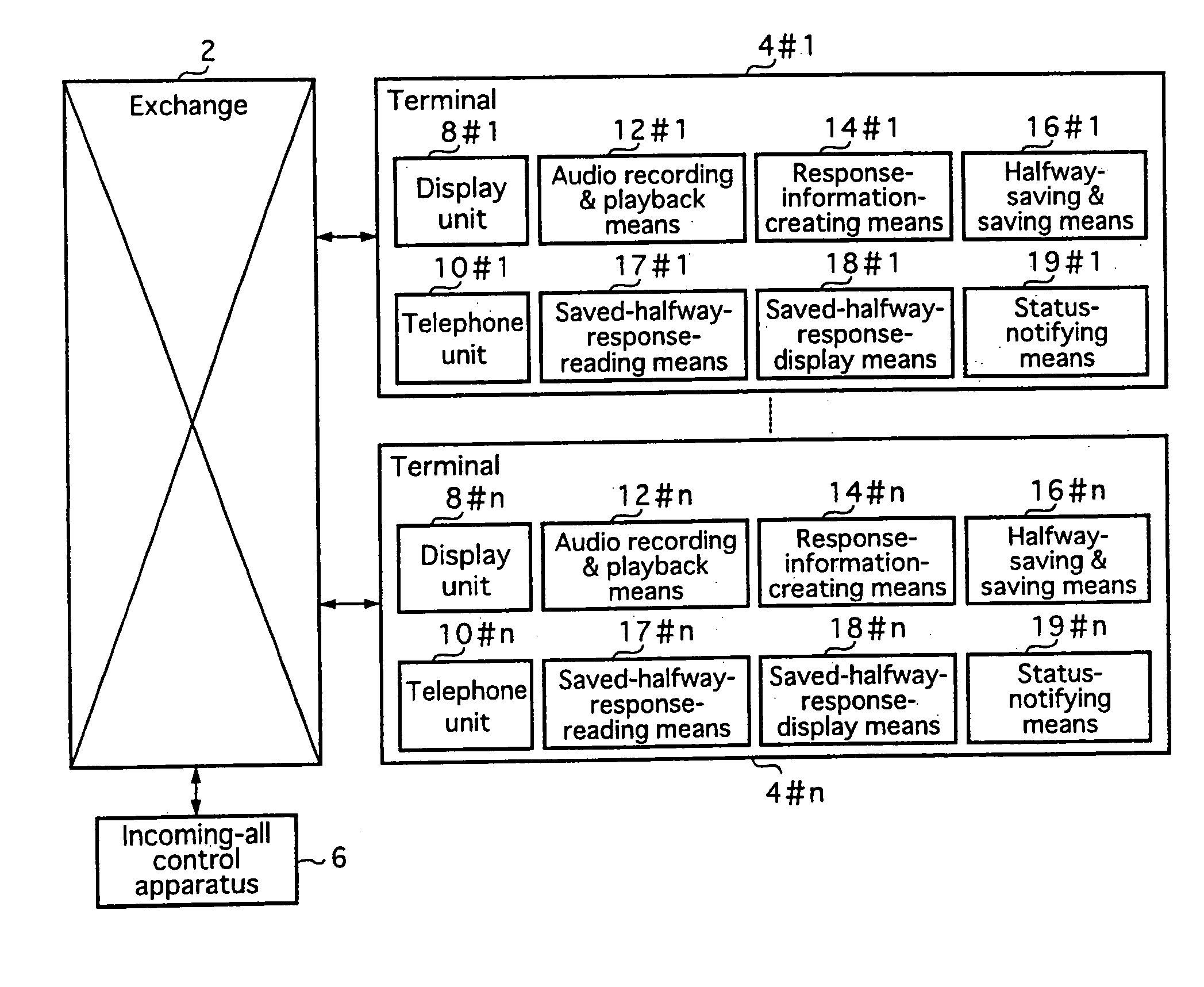
[0032] Before preferred embodiments of the present invention are explained, the principle of the invention is described. FIG. 1 is a diagram showing the principle of the present invention. As shown in FIG. 1, a call center system comprises an exchange 2, a plurality of terminals 4#i where i=1 to n accommodated by the exchange 2 and an incoming-call control apparatus 6. Each of the terminals 4#i comprises a display unit 8#i, a telephone unit 10#i, an audio recording & playback means 12#i, a response-information-creating means 14#i, a halfway-saving & saving means 16#i, a saved-halfway-response-reading means 17#i, a saved-halfway-response-display means 18#i and a status-notifying means 19#i. The exchange 2 informs the incoming-call control apparatus 6 of the arrival of an incoming call from an external source such as a public network. The incoming-call control apparatus 6 is monitoring the receivable state of each terminal 4#i. If a terminal 4#i in a receivable state is detected, the ...


PUM


Abstract

A call center system used for receiving incoming calls in accordance with the present information has a plurality of terminals, an incoming-call control apparatus and an exchange. Each of the terminals is accommodated by the exchange and includes a display unit as well as a telephone unit; an audio recording & playback unit for recording voices of a conversation between an operator operating the terminal and a caller making an call in a conversation-voice recording file and for playing back voices from the conversation-voice recording file and a response-information-creating unit for creating a response to an incoming call. Further each of the terminals includes a halfway-saving & saving unit for saving a halfway response being created in a halfway-response recording file and for saving a completed response in a response recording file; a saved-halfway-response-reading unit for reading out the halfway response from the halfway-response recording file; a saved-halfway-response-display unit for displaying a halfway response stored in the halfway-response recording file read out by the saved-halfway-response-reading unit on the display unit; and a status-notifying unit for reporting status of being able or unable to receive an incoming call to the incoming-call control apparatus.

Description

CROSS REFERENCE TO RELATED APPLICATIONS [0001] This application is a divisional of U.S. application Ser. No. 10 / 746,198 filed on Dec. 26, 2003, now pending, which is a divisional of U.S. application Ser. No. 09 / 805,389 filed Mar. 13, 2001, now U.S. Pat. No. 6,711,254, and claims priority from Japanese Patent Application 2000-326457 filed Oct. 26, 2000, the contents of which are herein incorporated by reference.BACKGROUND OF THE INVENTION [0002] 1. Field of the Invention [0003] In general, the present invention relates to a call center system for receiving phone calls. More particularly, the present invention relates to balanced distribution of loads to receive incoming call among operators working at the call center system. [0004] 2. Description of the Related Art [0005] In recent years, there has been increasing the number of enterprises each setting a call center system for receiving phone calls for, among other purposes, improvement of services to give a fast response to an inqui...

Claims


Application Information

Patent Timeline
IPC IPC(8): H04M5/00H04M3/42H04M3/51H04M3/523H04M3/533H04Q3/58
CPCH04M3/42221H04M3/523H04M3/5183H04M3/51
Inventor SATO, KAZUAKIKOIKE, TAKAYASUKIIRE, HIROYUKI
Owner FUJITSU LTD
Learn More