Card brace forming apparatus

Inactive Publication Date: 2007-09-13
HILLTOP INVESTMENTS
View PDF24 Cites 5 Cited by
  • Summary
  • Abstract
  • Description
  • Claims
  • Application Information

AI Technical Summary

Benefits of technology

[0010] There are a number of advantages to the apparatus including its simple,

Problems solved by technology

Usually, such cards are supposed to be self-supporting, that is, the cards support themselves, but they tend not to be very stable.
Many people

Method used


Image

  • Card brace forming apparatus
  • Card brace forming apparatus
  • Card brace forming apparatus

Examples


Example

[0030] While the present invention is open to various modifications and alternative constructions, the preferred embodiments illustrating the best mode contemplated by the inventors of carrying out their invention are shown in the various figures of the drawing and will be described herein in detail, pursuant to Title 35 U.S.C. section 112 (first paragraph). It is understood, however, that there is no intention to limit the invention to the particular embodiments, forms or examples which are disclosed herein. To the contrary, the intention is to cover all modifications, equivalent structures and methods, and alternative constructions falling within the spirit and scope of the invention as defined in the appended Claims section attached hereto, pursuant to Title 35 U.S.C. section 112 (second paragraph).

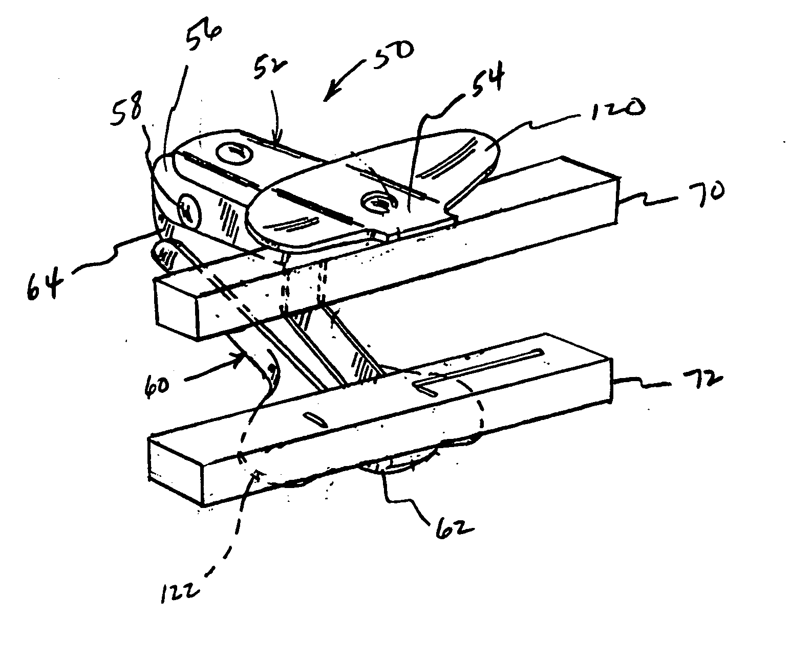
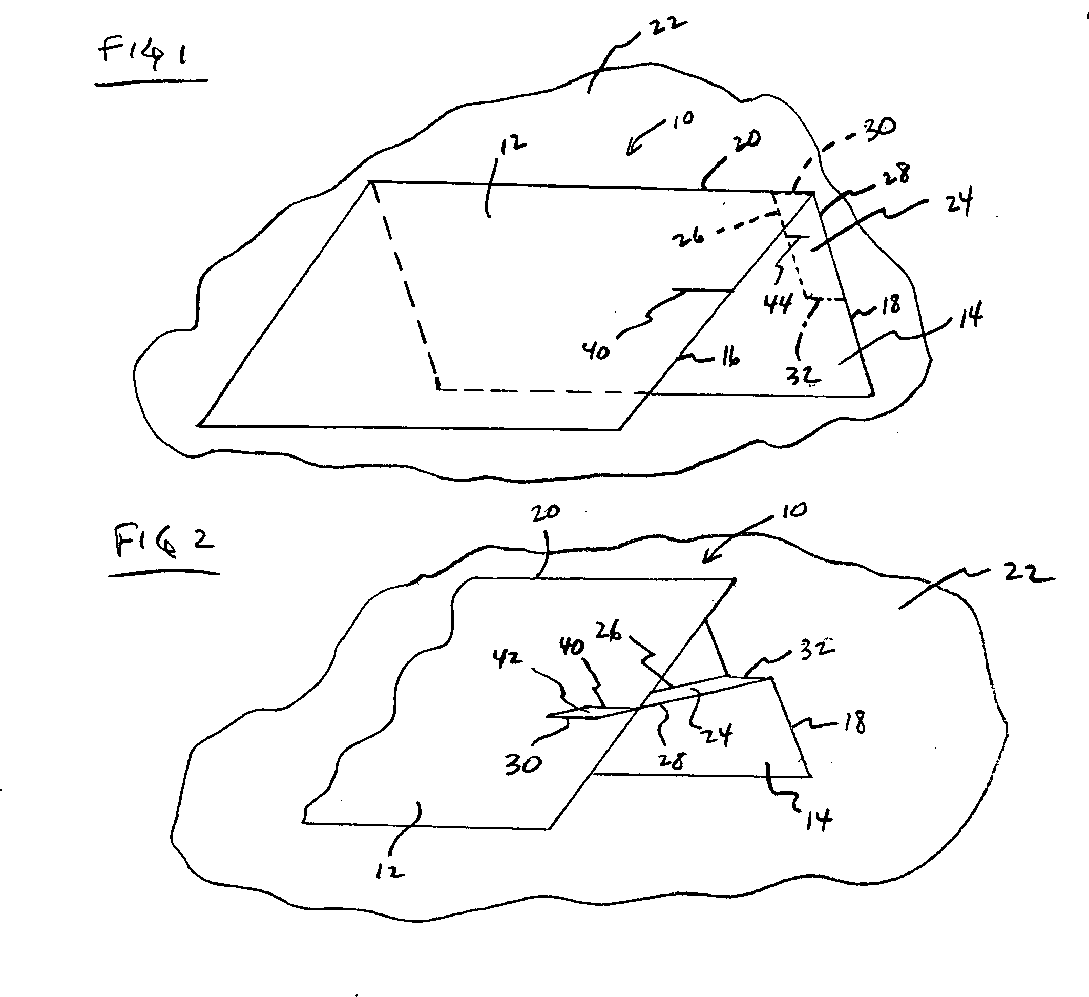
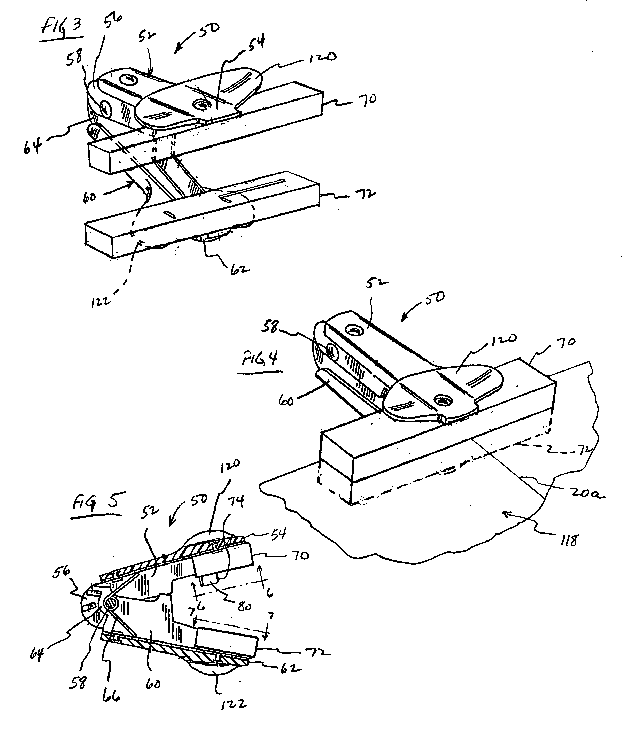
[0031] The above mentioned application Ser. No. ______ describes among other things a greeting and place card which may have a brace formed from part of the card. An example of such a...


PUM


Abstract

An apparatus for perforating or cutting and scoring paper cards, such as greeting and place cards. The apparatus includes hinged first and second arms held open by a spring. A die and a platen are attached to the arms and include a long blade, two spaced apart short blades, a scoring bar and spacer bars. An edge of a card is placed between the die and the platen against the spacer bars and when the arms are brought together, the card is cut and scored so that a brace is formed from one of the card panels. The brace is separable and may extend from one panel to another to provide support for the card when the card is displayed. The apparatus may be hand held and hand operated or the die and platen may be attached to powered stamping equipment.

Description

CROSS REFERENCE TO RELATED APPLICATIONS [0001] Not applicable. STATEMENT REGARDING FEDERALLY SPONSORED RESEARCH [0002] Not applicable. BACKGROUND OF THE INVENTION [0003] 1. Field of the Invention [0004] The present invention relates to a brace forming apparatus and more particularly to a card brace forming apparatus, which may be machine operated or hand held and hand operated, for perforating or cutting a portion of, for example, a paper card such as a greeting or place card to form a brace and enable the stable display of the card. [0005] 2. Description of the Related Art [0006] As explained in co-pending application entitled “Support System For A Paper Card And Method Of Forming Same”, application Ser. No. ______ (Attorney Docket No. 694895-600001), filed on even date with the present application, and incorporated herein by reference in its entirety, cards in the form of greeting cards are often displayed in a partially opened or “A-frame” position on a mantle or shelf, especiall...

Claims


Application Information

Patent Timeline
IPC IPC(8): B26B13/00
CPCB26D3/12B26F1/22B26F1/18B26D5/10
Inventor VICK, T. KEVINVICK, DOUGLAS M.
Owner HILLTOP INVESTMENTS
Why Eureka
Try Eureka