In-situ large area optical strain measurement using an encoded dot pattern

a large area, optical strain technology, applied in the direction of force measurement, force measurement, force measurement, etc., can solve the problems of small area for strain measurement and inconvenient large area measuremen

Active Publication Date: 2007-09-13
NORTHROP GRUMMAN SYST CORP
View PDF18 Cites 37 Cited by
  • Summary
  • Abstract
  • Description
  • Claims
  • Application Information

AI Technical Summary

Problems solved by technology

The limitation of these systems is that they can only provide strain measurement in a small area, or the strain is averaged over a large area and d...

Method used


Image

  • In-situ large area optical strain measurement using an encoded dot pattern
  • In-situ large area optical strain measurement using an encoded dot pattern
  • In-situ large area optical strain measurement using an encoded dot pattern

Examples


Embodiment Construction

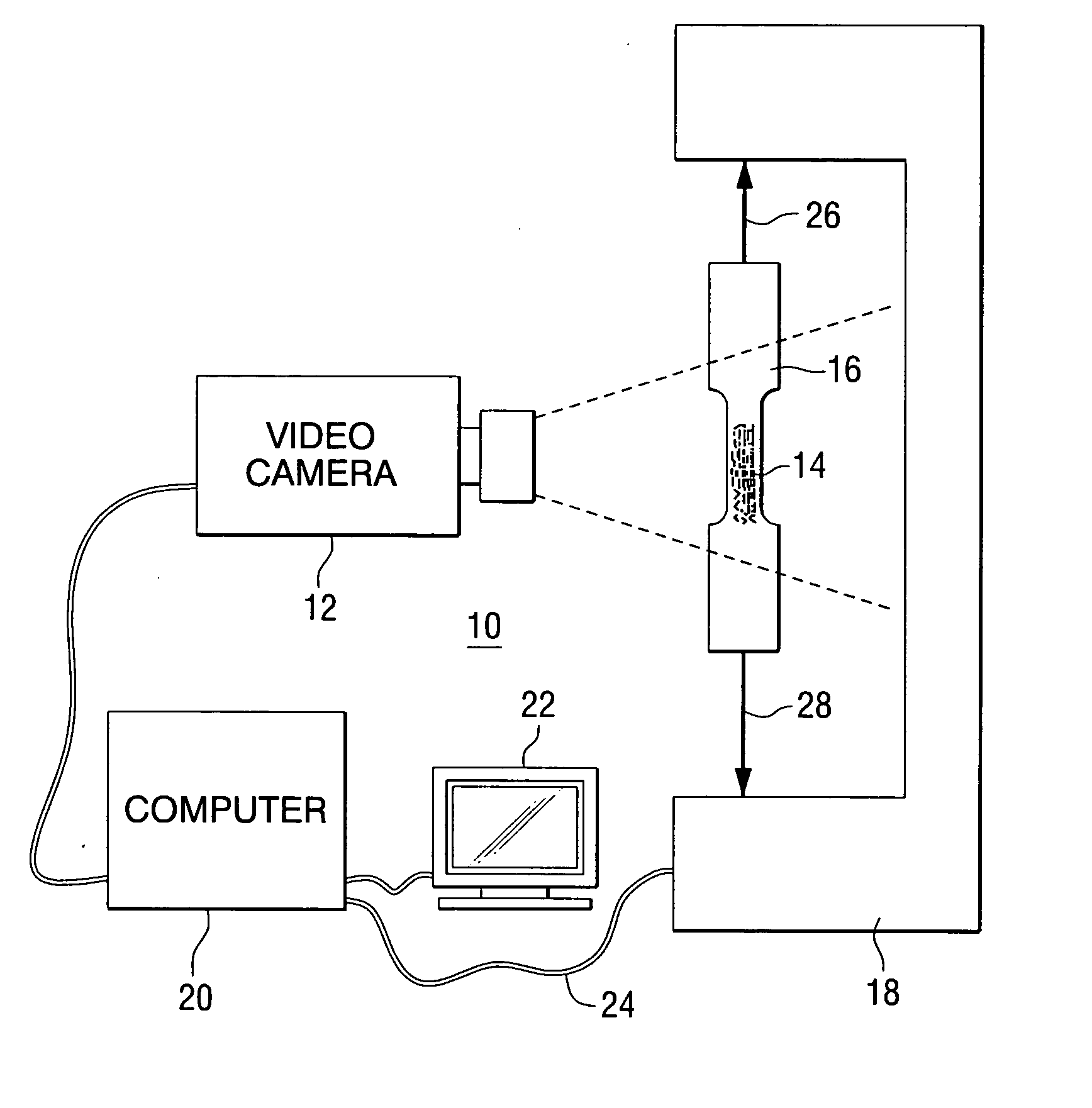
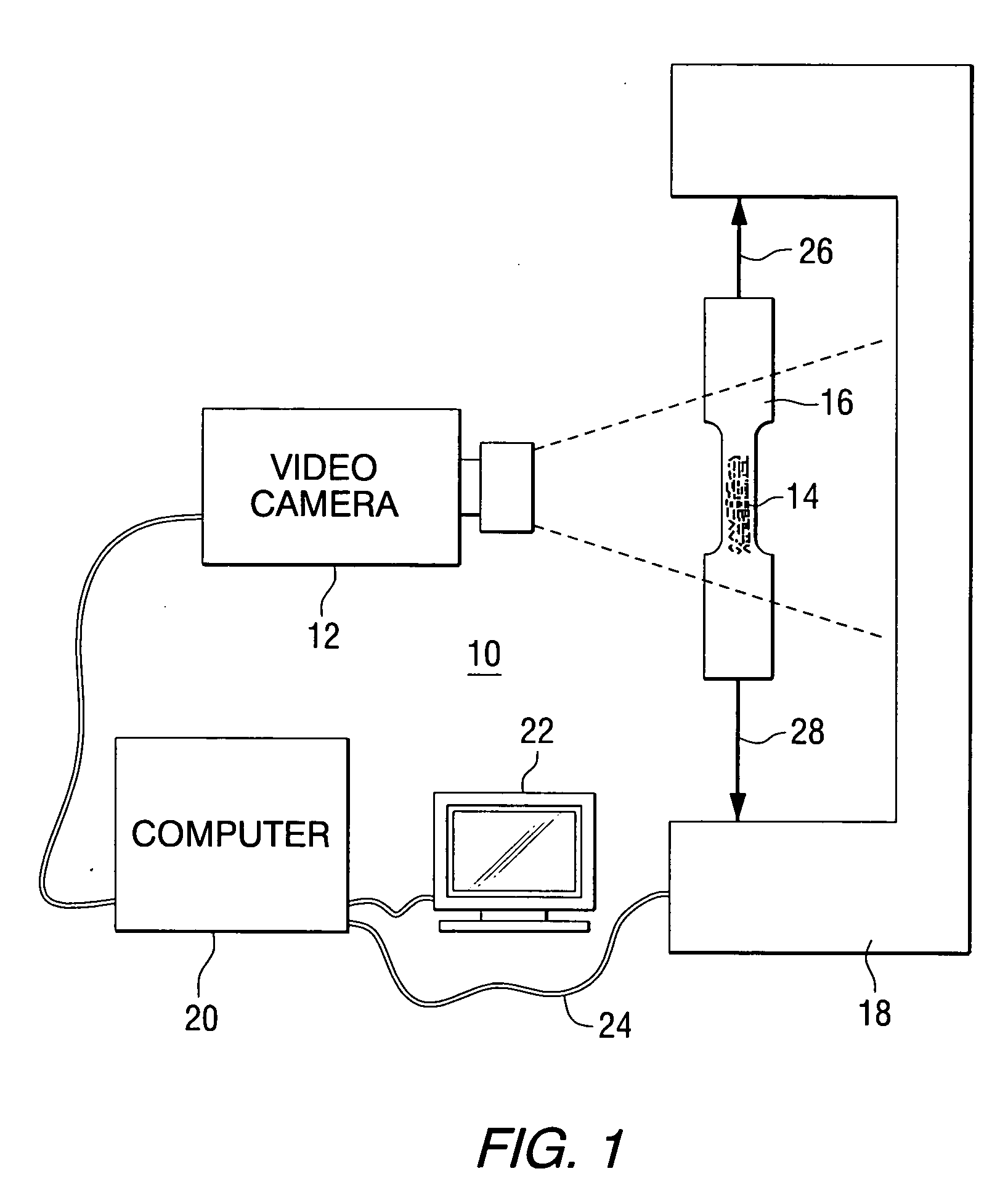
[0012] This invention provides a method and apparatus for non-contact strain measurement of a work piece or test specimen. FIG. 1 is a schematic representation of a strain measurement system 10 constructed in accordance with the invention. The system includes an imaging device, such as a video camera 12 positioned to capture images of a pattern 14 of marks on a surface of a work piece or test specimen 16. In this example, the test specimen is mechanically connected to a load application device 18 that is used to place a mechanical load on the test specimen, resulting in deformation of the test specimen and changes in the images captured by the video camera. Image information is sent from the video camera to an acquisition and control computer 20, which processes the information and produces an output that is representative of the mechanical strain in the test specimen. The output is displayed on a user interface 22. A feedback loop 24 is also provided to permit control of the load a...


PUM


Abstract

A method of measuring strain in a test specimen comprises the steps of placing a pattern of marks on a surface of the test specimen, wherein the pattern of marks includes a plurality of target marks and a plurality of sets of coded marks, using the sets of coded marks to identify locations of at least two of the target marks, and using a change in distance between at least two of the marks to determine strain in the test specimen. An apparatus that performs the method is also provided.

Description

FIELD OF THE INVENTION [0001] This invention relates to methods and apparatus for measuring strain in a test specimen, and more particularly to methods and apparatus for measuring strain over a large area of the test specimen. BACKGROUND OF THE INVENTION [0002] During structural testing, it is often of interest to measure the imposed mechanical strains for either documentary purposes or for control of the test. The most common systems used for strain measurement are extensometers or strain gages, which are devices that are mounted in contact with the test specimen. [0003] In some cases it is desirable to have a non-contact strain measurement system. Such systems are commercially available and typically require registration marks to be placed or projected onto the specimen. The limitation of these systems is that they can only provide strain measurement in a small area, or the strain is averaged over a large area and does not provide information about two-dimensional strain variation...

Claims


Application Information

Patent Timeline
IPC IPC(8): G01L1/24
CPCG01L1/247
Inventor CHRIST, ROBERT J. JR.NARDIELLO, JERRELL ANTHONYPAPAZIAN, JOHN M.MADSEN, JOHN STEVEN
Owner NORTHROP GRUMMAN SYST CORP
Why Eureka
Try Eureka