Eureka AIR delivers breakthrough ideas for toughest innovation challenges, trusted by R&D personnel around the world.

Method of making a ball chain

a technology of ball chains and chain springs, applied in the field of ball chains, can solve the problems of chain server deformation, adversely affecting the rolling motion of steel balls, and too complicated production, and achieve the effect of improving the effect of spacers

Inactive Publication Date: 2007-09-13
HIWIN TECH
View PDF6 Cites 0 Cited by
  • Summary
  • Abstract
  • Description
  • Claims
  • Application Information

AI Technical Summary

Benefits of technology

[0008] The primary objective of the present invention is to provide a method of making a ball chain, which can solve the difficulties in production and can improve the effect of spacers for separating the steel balls.
[0009] Since all points on a spherical surface are equidistant from the center of its sphere, the occurrence of interference can be prevented during mold release by releasing the half sphere along the normal direction of a plane passing through the center of the sphere.
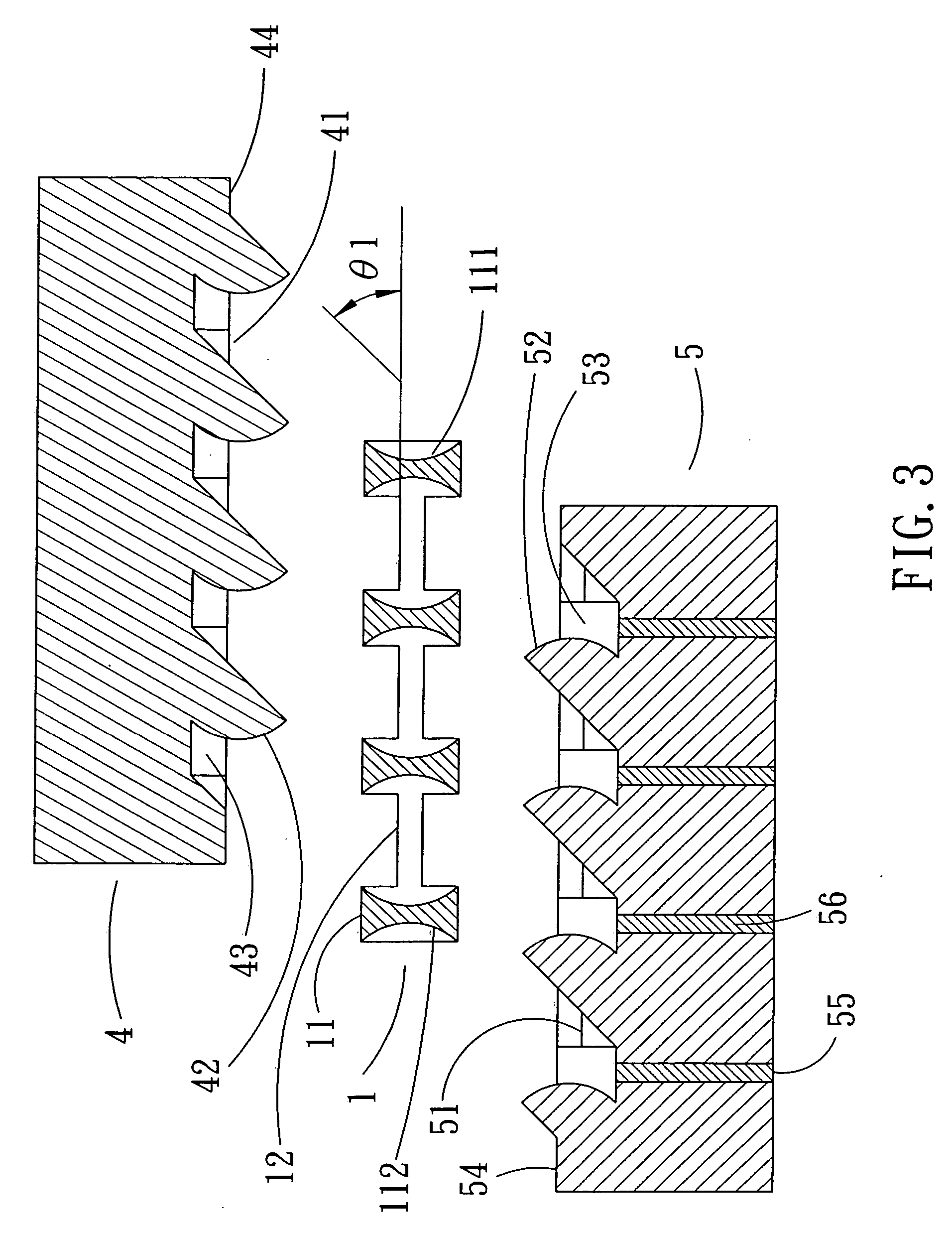
[0015] Since all points on a spherical surface are equidistant from the center of its sphere, the occurrence of interference can be prevented during mold release by releasing the half sphere along the normal direction of a plane passing through the center of the sphere. And the two half molds (upper and lower molds) of the present invention are released along the normal direction of a plane passing through the center of the sphere, such mold releasing method can solve the difficulties in production and can improve the effect of spacer for separating the steel balls.

Problems solved by technology

Due to using steel balls as a core, plus a ball chain usually comprises tens of spacers, that is, tens of spacers all need to serve as mold cores, the conventional method of making ball chain requires too many molds, and the resultant production is too complicated.
However, due to the interference strength between the mold and the ball chain is very great, it will lead to a server deformation of the chain during the mold releasing process (the finished product is lengthened).
If increasing the interference of the steel balls with respect to the spacers and reducing the interference strength between the mold and the ball chain, it will adversely affect the rolling motion of the steel balls.

Method used


Image

  • Method of making a ball chain
  • Method of making a ball chain
  • Method of making a ball chain

Examples


Embodiment Construction

[0028] The foregoing, and additional objects, features and advantages of the present invention will become apparent from the following detailed description of preferred embodiments thereof, taken in conjunction with the accompanying drawings.

[0029]FIG. 3 is an illustrative view of showing a ball chain 1 made by the method in accordance with the present invention, and an upper mold 4 and a lower mold 5 for making the ball chain 1. The ball chain 1 in FIG. 3 comprises a plurality of spacers 11 (for easy description, only four spacer 11 are illustrated, but in fact, a ball chain may comprises tens of spacers 11), and a connecting member 12 connected at either side of the respective spacers 11 for connecting the spacers 11 together in a string fashion. Each two neighboring spacers 11 define a space for holding a steel ball (not shown), and each spacer 11 defines a concave 111, 112 in either side thereof for mating with the steel ball 2, so that a plurality of steel balls 2 can freely r...


PUM

PropertyMeasurementUnit
inclined angleaaaaaaaaaa
inclined angle θ1aaaaaaaaaa

Abstract

Since all points on a spherical surface are equidistant from the center of its sphere, the occurrence of interference during mold release can be prevented by releasing the half sphere along the normal direction of a plane passing through the center of the sphere. In this invention, the upper and lower molds of the ball chain each has a protruding configuration having a spherical surface, and the upper and lower molds are released along an inclined direction, thus preventing the interference between the protruding configuration and the finished product during mold release. Such mold releasing method also can solve the difficulties in production and can improve the effect of the spacers for separating the steel balls.

Description

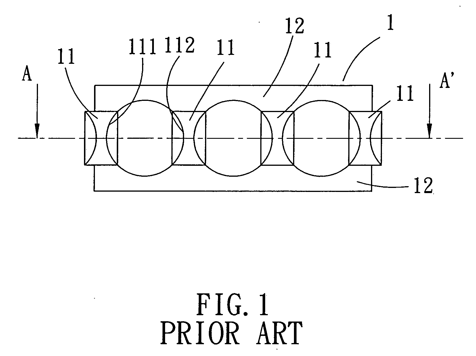
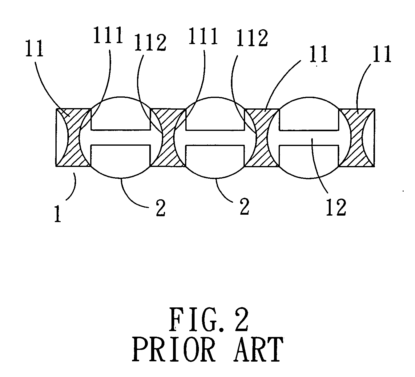
BACKGROUND OF THE INVENTION [0001] 1. Field of the Invention [0002] The present invention relates to a ball chain that is used in a rolling mechanism for preventing the steel balls from colliding with each other, and more particularly to a method for making such a ball chain. [0003] 1. Description of the Prior Art [0004]FIG. 1 is a front view of showing a conventional ball chain, FIG. 2 is a cross sectional view of the ball chain taken along the line A-A′ of FIG. 1. The ball chain 1 comprises a plurality of spacers 11, and a connecting member 12 is connected at either side of the spacers 11, so that the spacers 11 are connected in a string. Each two neighboring spacers 11 define a space for holding a steel ball 2, and each spacer 11 defines a concave 111, 112 in either side thereof for mating with the steel ball 2, so that a plurality of steel balls 2 can freely roll within the spaces defined by the spacers 11 without impacting each other. A ball chain is generally designed to have ...

Claims


Application Information

Patent Timeline
Patent Type & Authority Applications(United States)
IPC IPC(8): B29C45/00
CPCB29C45/14754
Inventor KUO, CHANG-HSIN
Owner HIWIN TECH
Why Eureka
Eureka Blog
Learn More