Method for determining pump flow without the use of traditional sensors

Active Publication Date: 2007-09-13
ITT MFG ENTERPRISES LLC
View PDF24 Cites 117 Cited by
  • Summary
  • Abstract
  • Description
  • Claims
  • Application Information

AI Technical Summary

Benefits of technology

[0024]The power equation may, for example, include a 3rd order polynomial equation developed using coefficients from a normalized power versus flow curve, and corrections may be made for speed and hydraulic efficiency in the polynomial power equation. In addition, complex roots may be determined to solve the 3rd order polynomial equation using either Muller's method or some other suitable method, and the calculated actual flow may be de

Problems solved by technology

This is necessary because published performance data often differs

Method used


Image

  • Method for determining pump flow without the use of traditional sensors
  • Method for determining pump flow without the use of traditional sensors
  • Method for determining pump flow without the use of traditional sensors

Examples


Embodiment Construction

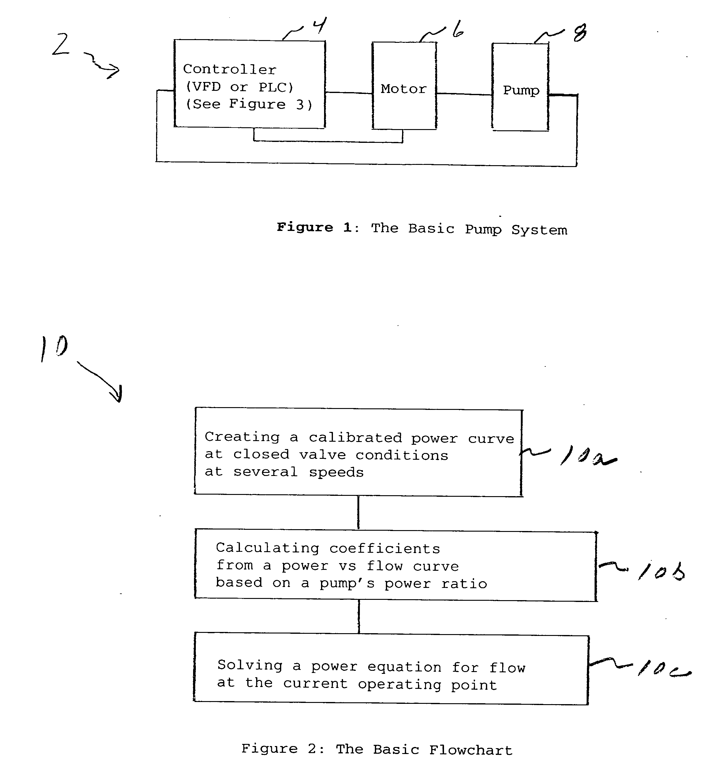
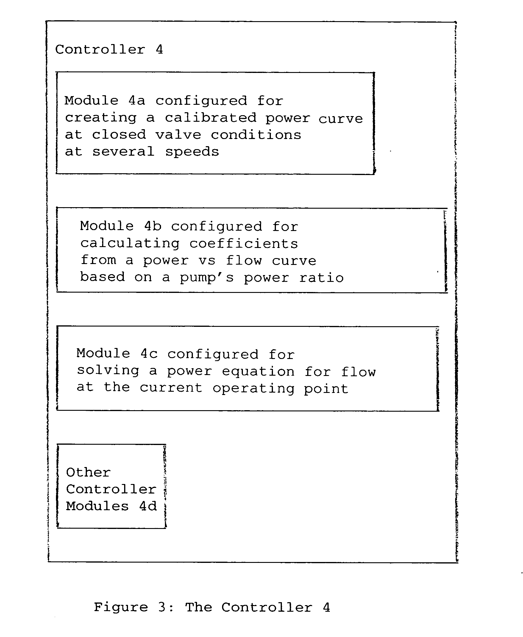
[0036]FIG. 1 shows the basic pump system generally indicated as 2 according to the present invention, having a controller 4, a motor 6 and a pump 8. In operation, and according to the present invention, the controller 4 provides for determining pump flow without using traditional sensors based on a technique of creating a calibrated power curve at closed valve conditions at several speeds; calculating coefficients from a power vs flow curve based on a pump's power ratio; and solving a power equation for flow at the current operating point, consistent with that shown and described herein.

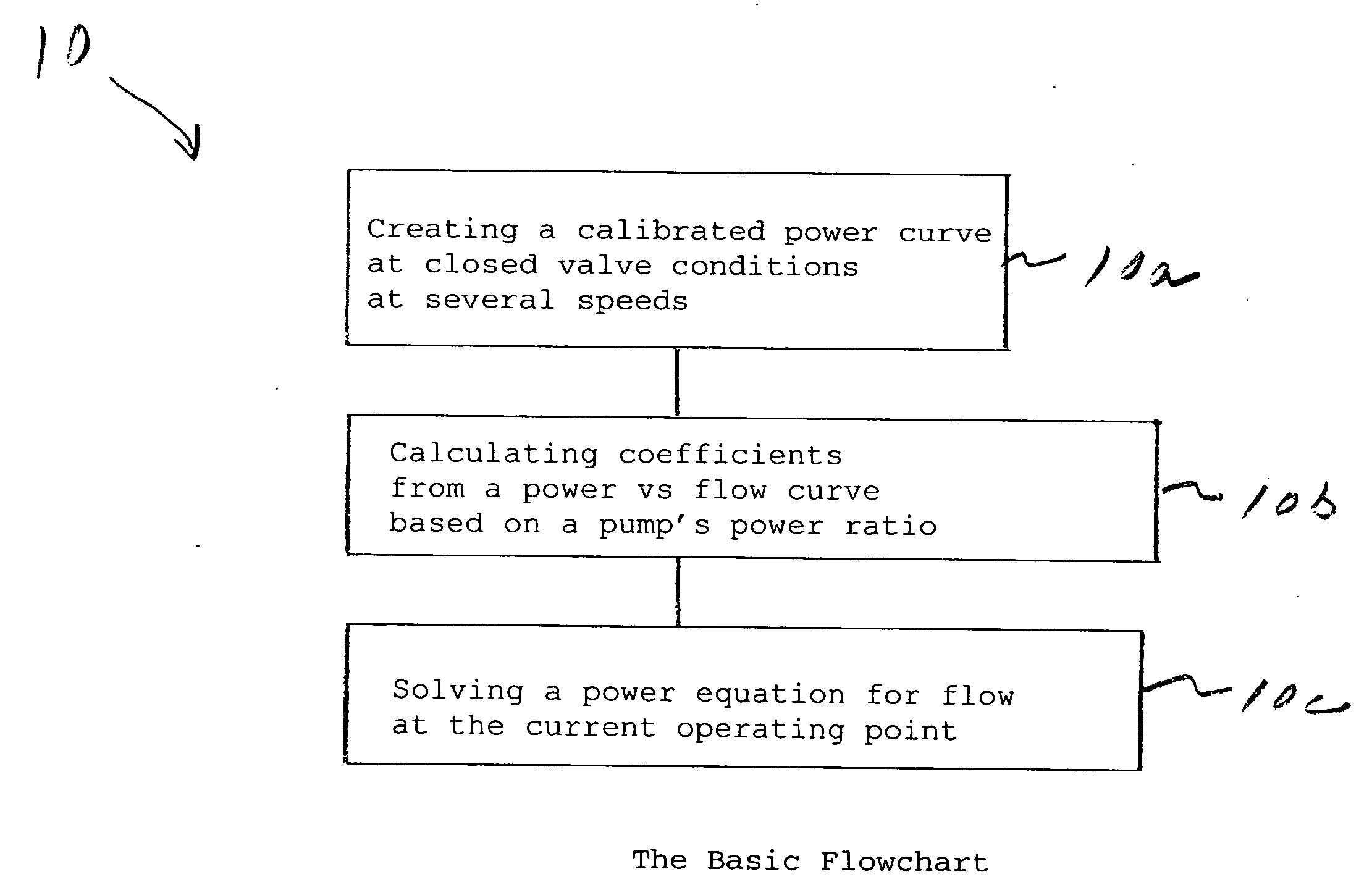
[0037]FIG. 2 shows, by way of example, a flowchart generally indicated as 10 having the basic steps 10a, 10b, 10c of the pump flow determination algorithm that may be implemented by the controller 4 according to the present invention. The determined flow value may also be used as an input to a PID control loop to control flow without an external flowmeter or traditional instrumentation. The flow dete...


PUM


Abstract

A technique for determining pump flow without using traditional sensors features steps and modules for creating a calibrated power curve at closed valve conditions at several speeds; calculating coefficients from a normalized power curve based on a pump's power ratio; and solving a polynomial power equation for flow at the current operating point. The calibrated power curve may be created by increasing the speed of the pump from a minimum speed to a maximum speed and operating the pump with a closed discharge valve. This data is used to correct published performance for shutoff power and best efficiency point power at rated speed in order to determine the pump's power ratio. It is also used to accurately determine closed valve power at the current operating speed. The pump's power ratio is determined by the equation: Pratio=Pshutoff @100%/PBEP<sub2>—</sub2>corr. The polynomial power equation may, for example, include a 3rd order polynomial equation developed using coefficients from the normalized power versus flow curve, and corrections may be made for speed, hydraulic efficiency and specific gravity in the polynomial power equation. Complex roots may be determined to solve the 3rd order polynomial equation using either Muller's method or some other suitable method, and the calculated actual flow may be determined for a specific operating point.

Description

CROSS-REFERENCE TO RELATED APPLICATIONS[0001]This patent application claims benefit to provisional patent application Ser. No. 60 / 780,546, filed 8 Mar. 2006, entitled “Method for Determining Pump Flow Without the Use of Traditional Sensors,” (911-2.24-1 / 05GI003), and is also related to patent application Ser. No. 11 / 601,373, filed 17 Nov. 2006, entitled “Method and Apparatus For Pump Protection Without the Use of Traditional Sensors,” (911-2.22-1 / 05GI002), and is also related to provisional patent application Ser. No. 60 / 780,547, filed 8 Mar. 2006, entitled “Method for Optimizing Valve Position and Pump Speed in a PID Control Valve System without the Use of External Sensors” (911-2.23-1 / 06GI001). All of these patent applications are incorporated herein by reference in their entirety.BACKGROUND OF THE INVENTION[0002]1. Field of the Invention[0003]The present invention relates to a pump system having a pump, including a centrifugal pump; and more particularly to a method for determini...

Claims


Application Information

Patent Timeline
IPC IPC(8): F04D27/02
CPCF04D27/001F04D15/0088
Inventor KERNAN, DANIEL J.SABINI, EUGENE P.GANZON, NICOLAS W.STAVALE, ANTHONY E.
Owner ITT MFG ENTERPRISES LLC
Why Eureka
Try Eureka