Supercharge Your Innovation With Domain-Expert AI Agents!

Process for manufacturing insulated siding

a technology of insulating siding and manufacturing process, which is applied in the field of construction/wall covering art, can solve the problems of affecting the overall thermal properties of the building, and insulating vinyl or metal siding has very little insulative properties, so as to achieve the effect of easy manufacturing of siding products

Inactive Publication Date: 2007-09-13
CERTAINTEED CORP
View PDF9 Cites 33 Cited by
  • Summary
  • Abstract
  • Description
  • Claims
  • Application Information

AI Technical Summary

Problems solved by technology

However, siding made of vinyl or metal has very little insulative properties.
Although known insulated siding systems may provide improved thermal insulation properties over non-insulated siding systems, they still may allow significant airflow which may adversely affect the overall thermal properties of the building.
Additionally, foamed insulation boards offer very little compressibility and almost no resiliency to conform to surface variations or anomalies.
As a result of this, small spaces and air gaps are often found between the insulation board and the ornamental facing of the siding as well as between the insulation board and the sheeting to which the siding assembly is attached.
Such gaps and air spaces channel air around the insulation and tend to reduce the “R-rating” of the siding system.
Since conventional foam insulated siding typically has a low R-value, the beneficial effects of the insulated siding may be quickly degraded as a result.
In addition, foam insulation is relatively brittle and breaks easily.
As a consequence, it typically cannot be manufactured in thicknesses of less than 3 / 16 in.
As a result it is generally not practical to make an insulated siding panel assembly with foam insulation having a thickness of approximately ¾ in.
This is primarily due to the tapered profile of the siding, which in order to achieve ¾ inch maximum at the thickest point, results in a portion of the foam being tapered to less than 3 / 16 of an inch thick to fit into conventional standard ¾ inch trim (such as j-channels, window trim, etc)—which results in breakage and difficult manufacturing conditions.

Method used


Image

  • Process for manufacturing insulated siding
  • Process for manufacturing insulated siding
  • Process for manufacturing insulated siding

Examples


Embodiment Construction

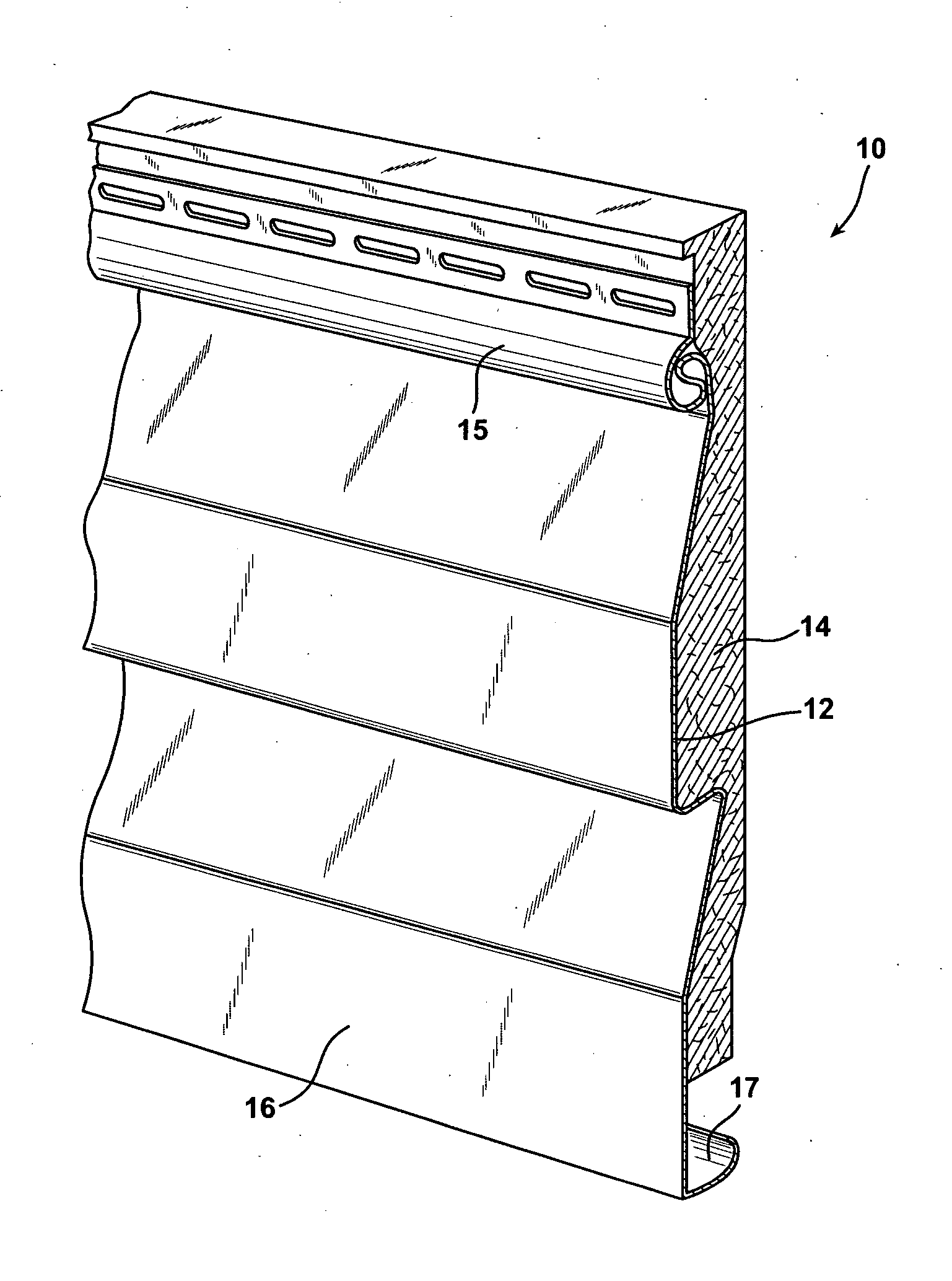
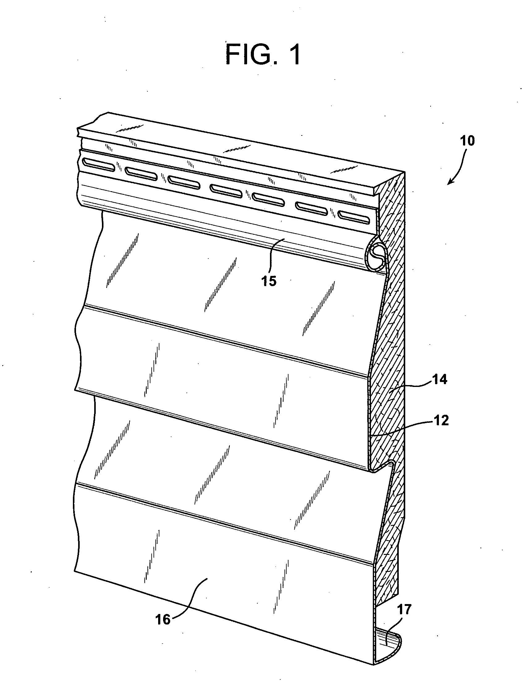
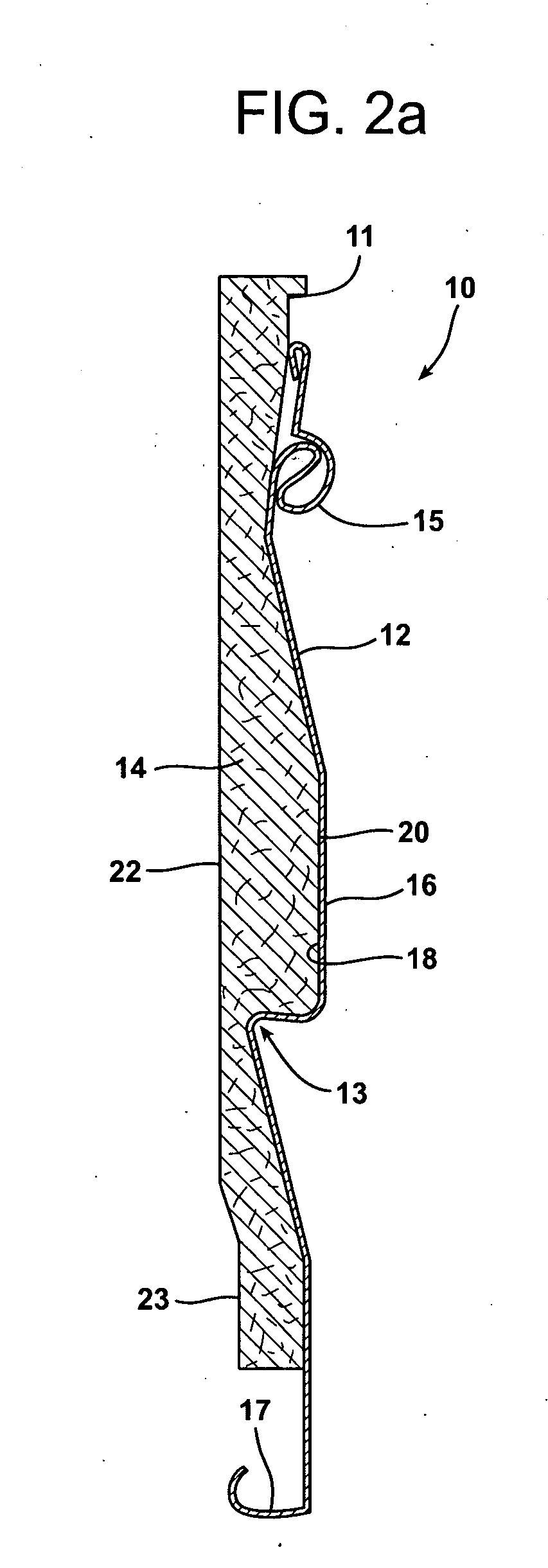
[0026] Reference is now made to FIG. 1 which illustrates the siding panel assembly 10 of the present invention. As illustrated in the FIG. 2a embodiment, the siding panel assembly 10 incorporates an ornamental facing 12 and a first insulation layer 14. The ornamental facing 12 preferably includes a tongue 15 at one end and a groove 17 at the opposite end to allow one siding panel assembly 10 to be connected to another by lapping margins in a manner well known in the art. The ornamental facing 16 may be constructed from any number of appropriate materials including but not limited to fiberglass, vinyl, polyvinyl chloride, aluminum, steel, ABS, other polymers, concrete, wood, natural fibrous materials, and mixtures thereof. The ornamental facing 12 may include an exposed, textured face 16 made, for example, to look like wood siding.

[0027] As further illustrated in FIG. 2a, the ornamental facing 12 includes a concavity formed by the contoured rear face 18. This shaping of the ornament...


PUM

PropertyMeasurementUnit
diameteraaaaaaaaaa
diameteraaaaaaaaaa
weight percentaaaaaaaaaa

Abstract

A siding panel assembly includes an ornamental facing and a first insulation layer made from fibrous insulating material. That fibrous insulating material is selected from glass fibers, polymer fibers, natural fibers and mixtures thereof having a compressive strength of between about 14 to about 220 pounds of force and a wet and dry recovery of at least 98%. A method for making the siding panel assembly includes the steps of molding a first surface of a sheet of fibrous insulating material to match in profile a concavity in an ornamental facing and engaging the molded sheet of fibrous insulating material in that concavity.

Description

CROSS-REFERENCE TO RELATED APPLICATIONS [0001] This application is a continuation-in-part of co-pending application, U.S. Ser. No. 11 / 178,618 filed Jul. 11, 2005 which is incorporated by reference in its entirety.TECHNICAL FIELD AND INDUSTRIAL APPLICABILITY OF THE INVENTION [0002] The present invention relates generally to the construction / wall covering art and, more particularly, to an improved insulated siding system. BACKGROUND OF THE INVENTION [0003] Aluminum and vinyl siding has been used for years as exterior surface coverings on buildings such as residential homes to give the buildings aesthetically pleasing appearances. However, siding made of vinyl or metal has very little insulative properties. Thus, it is common practice to install an insulating board between the siding and the building frame. The insulating board is typically in the form of a core of a foamed polymeric material such as polyurethane, polyisocyanurate, a polyurethane modified polyisocyanurate, or a phenoli...

Claims


Application Information

Patent Timeline
Patent Type & Authority Applications(United States)
IPC IPC(8): B32B27/12D04H1/00
CPCB32B2307/102B32B2307/304B32B2310/028D04H1/42D04H1/48D04H1/54Y10T428/13D04H13/002D21H13/14D21H13/24D21H13/40D21H21/18D04H1/60D04H1/4218D04H1/43835Y10T442/608Y10T442/615Y10T442/631Y10T442/674Y10T442/677Y10T442/697
Inventor ROCKWELL, ANTHONY L.GRAHAM, W. DAVIDVERMILION, DONN R.CHAKRABARTY, KAUSHIK
Owner CERTAINTEED CORP
Features
  • R&D
  • Intellectual Property
  • Life Sciences
  • Materials
  • Tech Scout
  • Unparalleled Data Quality
  • Higher Quality Content
  • 60% Fewer Hallucinations
Learn More