Implantable medical electrode device, in particular cardiovascular cardiac pacemaker or defibrillator electrode device

Inactive Publication Date: 2007-09-13
BIOTRONIK SE & CO KG
View PDF9 Cites 22 Cited by
  • Summary
  • Abstract
  • Description
  • Claims
  • Application Information

AI Technical Summary

Benefits of technology

[0015]Proceeding therefrom, the present invention is based on the object of providing an elect

Problems solved by technology

Fixing in a blood vessel represents a special case, since sharp tips or edges of the fixing units may cause injuries or at least irritations on the vessel wall here in particular.
For this reason, typical fixing units are designed in such a way that they jam in the vessel because of their shaping.
An especially simple fixing technology, which does not achieve optimal therapeutic results, however, is wedging the distal tip of the electrode body in the vessel.
All of the preceding anchoring technologies have various disadvantages, such as the dependence of the final position of the electrode body on the ratio the diameter of the vein to the dimensions of the tip, helix anchors, or “tines”.
The final position of the electrode body thus achievable is not necessarily the most favorable therapeutic position.
This solution has

Method used


Image

  • Implantable medical electrode device, in particular cardiovascular cardiac pacemaker or defibrillator electrode device
  • Implantable medical electrode device, in particular cardiovascular cardiac pacemaker or defibrillator electrode device
  • Implantable medical electrode device, in particular cardiovascular cardiac pacemaker or defibrillator electrode device

Examples


Embodiment Construction

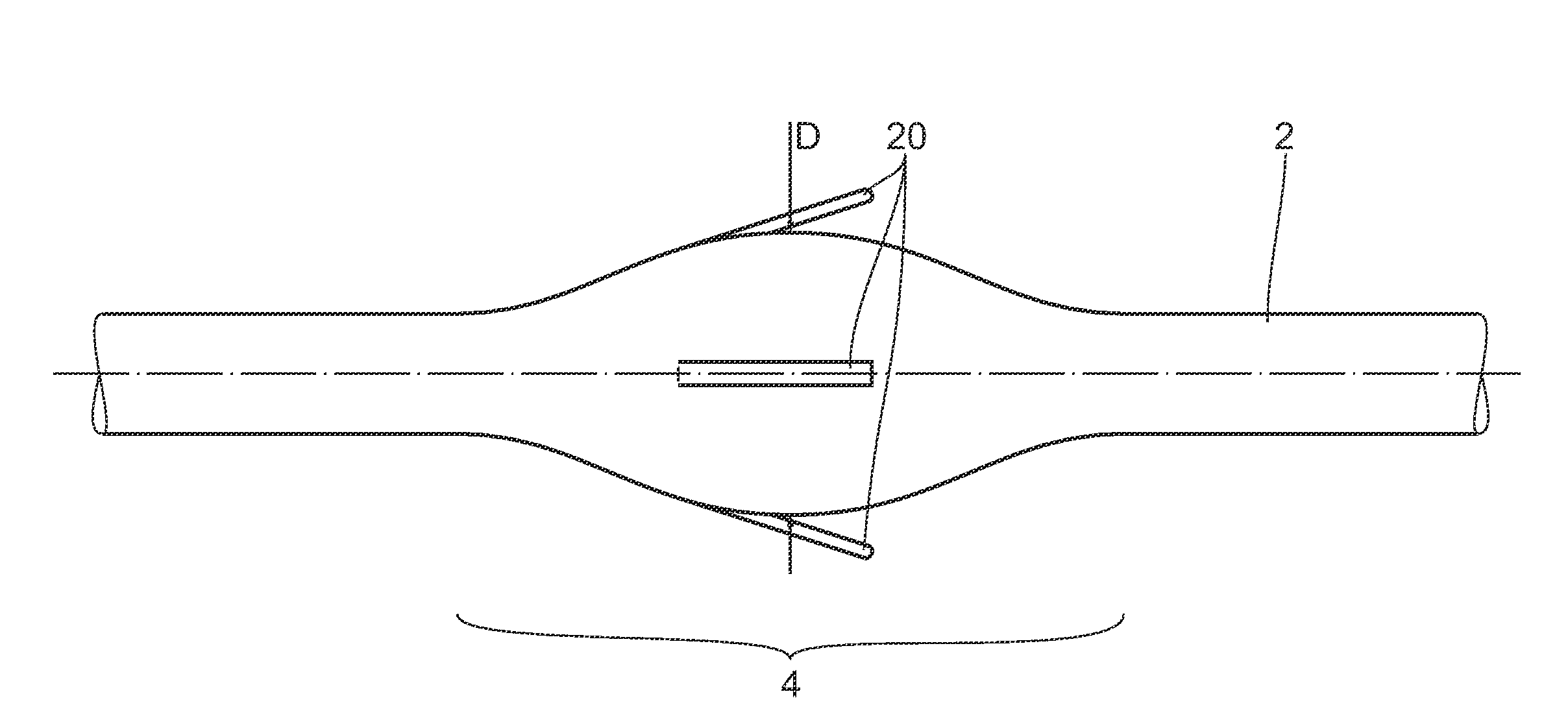
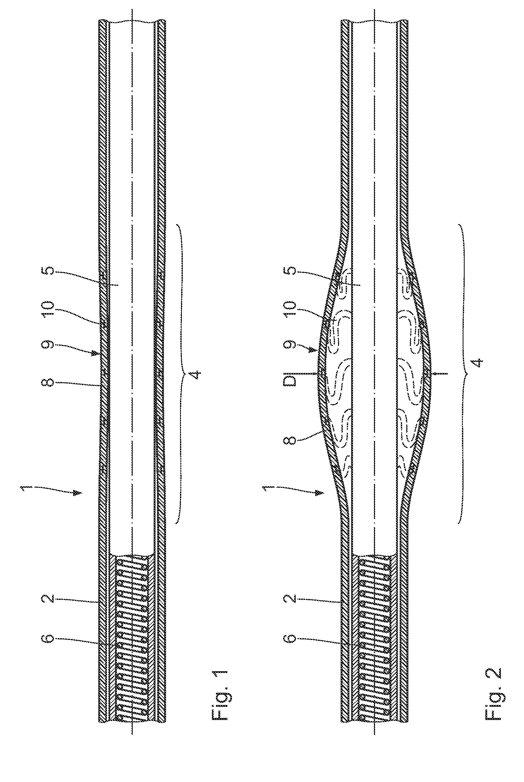
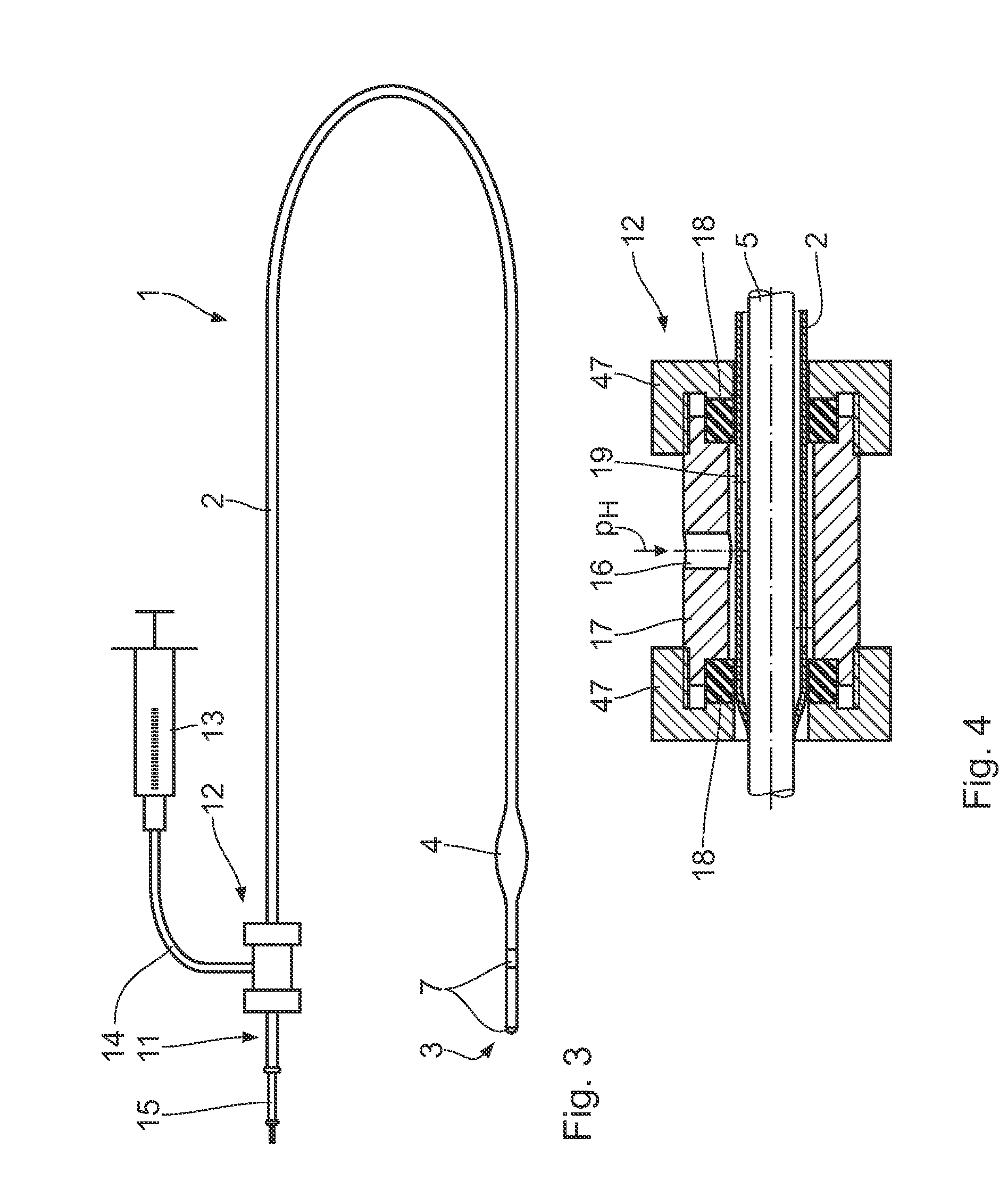
[0027]As is clear from FIGS. 1 and 2, an implantable medical electrode device in the form of a cardiac catheter, identified as a whole by 1, has an elongate, tubular electrode body 2, which is provided in front of the distal end 3 (FIG. 3) with a fixing zone 4, which is a few millimeters long. The coiled electrode supply lines 6, using which the stimulation electrodes 7 shown in FIG. 3 are supplied with voltage, for example, run in separate internal tubing 5 in the interior of the electrode body 2.

[0028]The wall 8 of the electrode body 2 is implemented as more flexible in the area of the fixing zone 4 than in the adjoining remaining areas. Furthermore, a stent-like, plastically deformable support structure 9 is embedded in the wall material therein. This support structure 9 is an essentially tubular, plastically deformable, expandable stretched metal or plastic molded part. The expansion forces of this support structure 9 are to be tailored by suitable material selection and texturi...


PUM


Abstract

An implantable medical electrode device, in particular a cardiovascular cardiac pacemaker or defibrillator electrode device, comprises an elongate, tubular electrode body (2), a fixing zone (4) in front of the distal end (3) of the electrode body (2), in which the externally closed peripheral envelope (8) of the electrode body (2) is reversibly expandable into a body lumen (27) for detachable fixing of the electrode device (1), and expansion means, situated in the fixing zone (4), for controlling the expansion and contraction in the fixing zone (4).

Description

[0001]This application takes priority from German Patent Application DE 10 2006 011 349.7 filed 11 Mar. 2006, the specification of which is hereby incorporated herein by reference.BACKGROUND OF THE INVENTION[0002]1. Field of the Invention[0003]The present invention relates to an implantable medical electrode device and, in particular, a cardiovascular cardiac pacemaker or defibrillator electrode device.[0004]2. Description of the Related Art[0005]On the background of the present invention, it is to be noted that implantable electrode devices of this type must be anchored at a specific body location, so that they do not change their position over the course of time. This is especially important when such electrode devices are implanted in a moving organ, such as the heart.[0006]To fix the electrode device, implementing fixing units, such as screws, needles, hooks, anchors (tines), or projections and corresponding undercuts, into which the tissue may grow, on their elongate, tubular e...

Claims


Application Information

Patent Timeline
IPC IPC(8): A61N1/05
CPCA61N1/057A61N2001/0585A61N2001/0578
Inventor DREIER, ECKARDFLACH, ERHARDGEISTERT, WOLFGANGMAXFIELD, MICHELLEPALM, JOCHENSCHURR, MARCBRINKMANN, JAN-HEINER
Owner BIOTRONIK SE & CO KG
Why Eureka
Try Eureka