Leadless Cardiac Pacemaker with Integral Battery and Redundant Welds

a technology of lead-free cardiac pacemakers and redundant welds, which is applied in the field of lead-less cardiac pacemakers, can solve the problems of subcutaneous pulse generators that can exhibit erosion, irritation, and discomfort of patients and prolong patient recovery. the effect of recovery

Active Publication Date: 2013-05-16
PACESETTER INC
View PDF12 Cites 167 Cited by
  • Summary
  • Abstract
  • Description
  • Claims
  • Application Information

AI Technical Summary

Benefits of technology

[0012]In some embodiments, the first and second sets of welds provide dual-weld redundancy.

Problems solved by technology

Although more than one hundred thousand conventional cardiac pacing systems are implanted annually, various well-known difficulties exist, of which a few will be cited.
For example, a pulse generator, when located subcutaneously, presents a bulge in the skin that patients can find unsightly, unpleasant, or irritating, and which patients can subconsciously or obsessively manipulate or “twiddle”.
Even without persistent manipulation, subcutaneous pulse generators can exhibit erosion, extrusion, infection, and disconnection, insulation damage, or conductor breakage at the wire leads.
Although sub-muscular or abdominal placement can address some concerns, such placement involves a more difficult surgical procedure for implantation and adjustment, which can prolong patient recovery.
This briefly described complex connection between connectors and leads provides multiple opportunities for malfunction.
Other problematic aspects of conventional pacemakers relate to the separately implanted pulse generator and the pacing leads.
By way of another example, the pacing leads, in particular, can become a site of infection and morbidity.
Sealing the battery compartment in a separate housing protects the patient from harm in the event that the battery compartment leaks, but increases the total size of the pacemaker by requiring a separate hermetic housing.

Method used


Image

  • Leadless Cardiac Pacemaker with Integral Battery and Redundant Welds
  • Leadless Cardiac Pacemaker with Integral Battery and Redundant Welds
  • Leadless Cardiac Pacemaker with Integral Battery and Redundant Welds

Examples


Embodiment Construction

[0045]Implantable leadless cardiac pacemakers or leadless biostimulators typically include a hermetic housing to contain all the necessary electrical components and to prevent any hazardous materials, such as battery electrolyte, from harming a patient in the event of a leak in the housing and / or battery. The hermetic housing can be used to encapsulate both the power source (e.g., battery) as well as the electronics compartment responsible for pacing / sensing of the pacemaker. However, the addition of a hermetic housing increases the size of a leadless biostimulator, making the biostimulator more difficult to implant and more invasive to the patient.

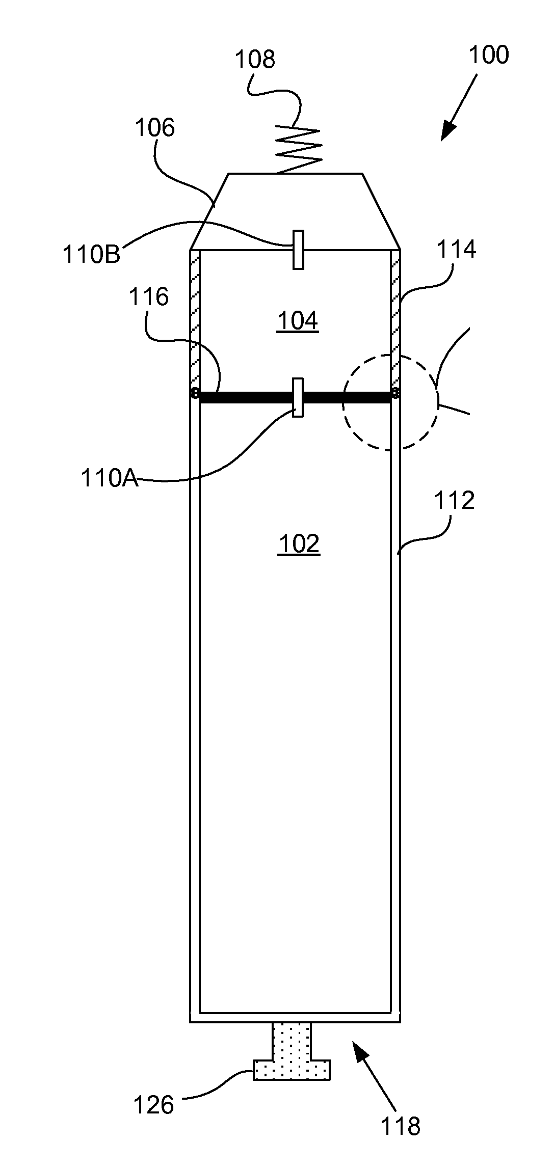
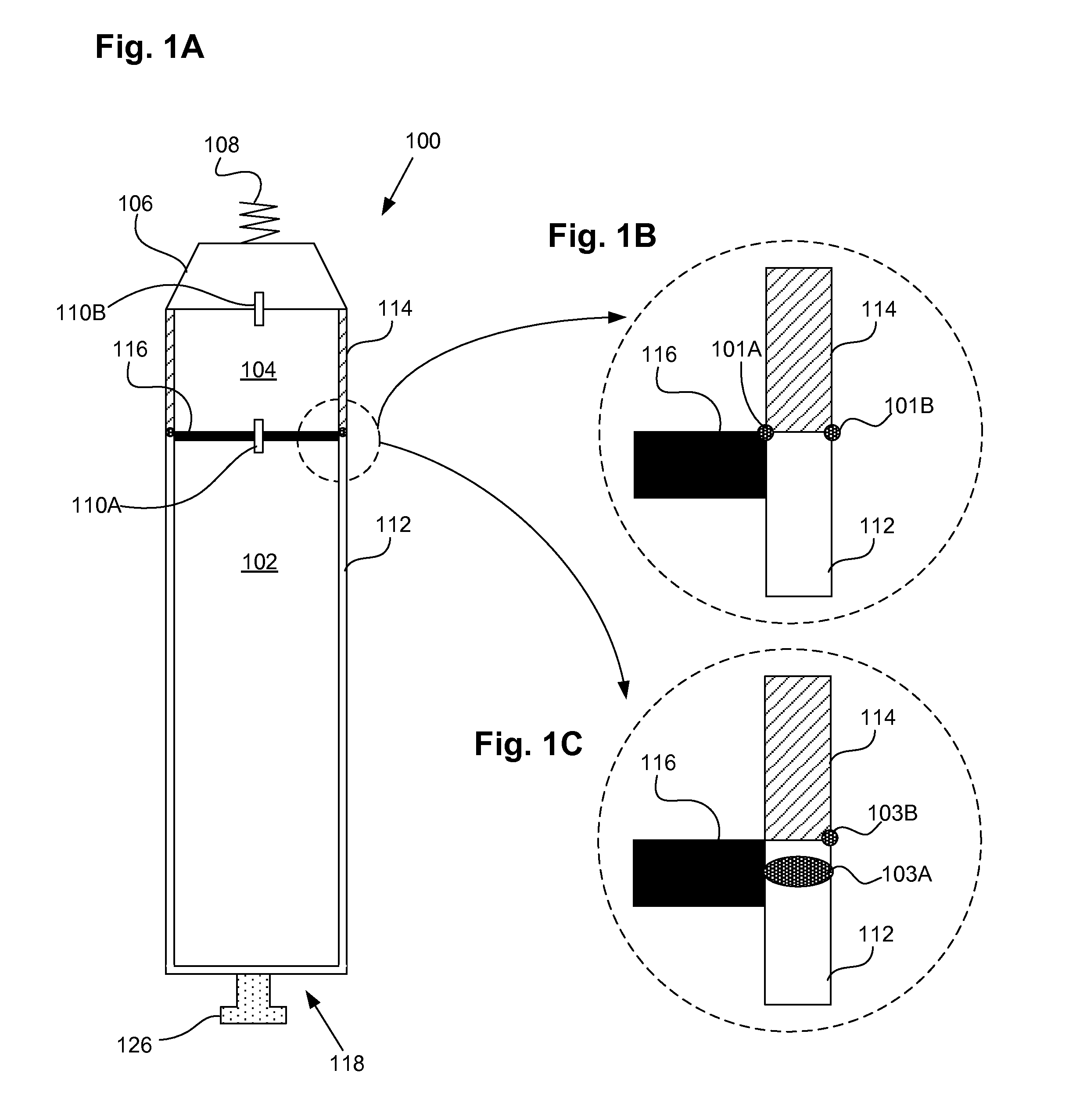
[0046]FIGS. 1A-1C shows a leadless cardiac pacemaker or leadless biostimulator 100. The biostimulator includes a hermetic battery 102, electronics compartment 104, header assembly 106, and fixation device 108. The fixation device 108 can be a fixation helix or other flexible or rigid structure suitable for attaching a distal portion of th...


PUM

PropertyMeasurementUnit
lengthsaaaaaaaaaa
inductanceaaaaaaaaaa
electricalaaaaaaaaaa

Abstract

A leadless cardiac pacemaker that does not require a separate hermetic housing surrounding the battery and electronics compartments is provided. The cardiac pacemaker can include a battery disposed in a battery housing and a set of electronics disposed in an electronics housing. In some embodiments, the battery housing and the electronics housing can comprise an external surface of the pacemaker. The pacemaker can include a first set of welds separating the battery from the set of electronics, and a second set of welds separating the set of electronics and the battery from an exterior of the housing. Various embodiments for achieving dual-redundant welds are also provided.

Description

CROSS REFERENCE TO RELATED APPLICATIONS[0001]This application claims the benefit of U.S. Provisional Patent Application No. 61 / 555,988, filed Nov. 4, 2011, titled “Leadless Cardiac Pacemaker with Integral Battery and Redundant Welds”, which application is incorporated herein by reference in its entirety.INCORPORATION BY REFERENCE[0002]All publications and patent applications mentioned in this specification are herein incorporated by reference to the same extent as if each individual publication or patent application was specifically and individually indicated to be incorporated by reference.FIELD[0003]The present disclosure relates to leadless cardiac pacemakers, and more particularly, to features and methods for welding and sealing the battery compartment to miniaturize the leadless pacemaker.BACKGROUND[0004]Cardiac pacing by an artificial pacemaker provides an electrical stimulation of the heart when its own natural pacemaker and / or conduction system fails to provide synchronized ...

Claims


Application Information

Patent Timeline
Patent Type & Authority Applications(United States)
IPC IPC(8): A61N1/375
CPCB23K26/206A61N1/3756A61N1/37512A61N1/37518A61N1/37205A61N1/3752A61N1/3968
Inventor VARADY, ERICOSTROFF, ALANJACOBSON, PETER M.
Owner PACESETTER INC
Why Eureka
Try Eureka