Blind type solar cell and array thereof

Inactive Publication Date: 2007-09-20
KOREA INST OF ENERGY RES
View PDF2 Cites 13 Cited by
  • Summary
  • Abstract
  • Description
  • Claims
  • Application Information

AI Technical Summary

Problems solved by technology

However, such an installation of the solar cell at the high place such as the roof as mentioned above causes inconvenience to manage the solar cell, and restriction in utility of the solar cell.

Method used


Image

  • Blind type solar cell and array thereof
  • Blind type solar cell and array thereof
  • Blind type solar cell and array thereof

Examples


Embodiment Construction

[0018] Preferred embodiments of the present invention will be described in detail with reference to the accompanying drawings.

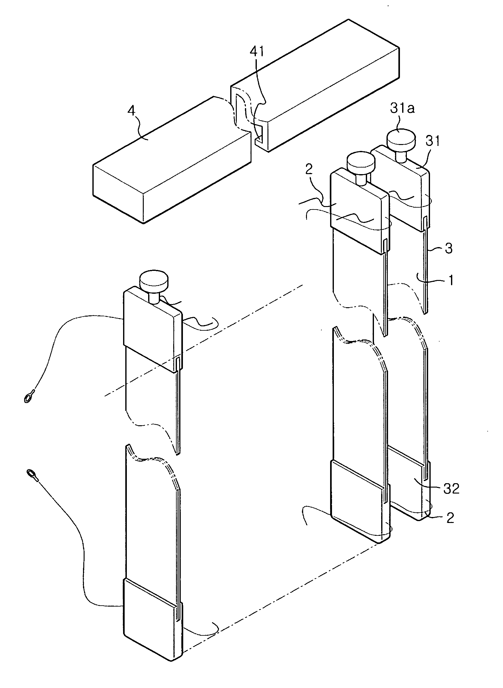
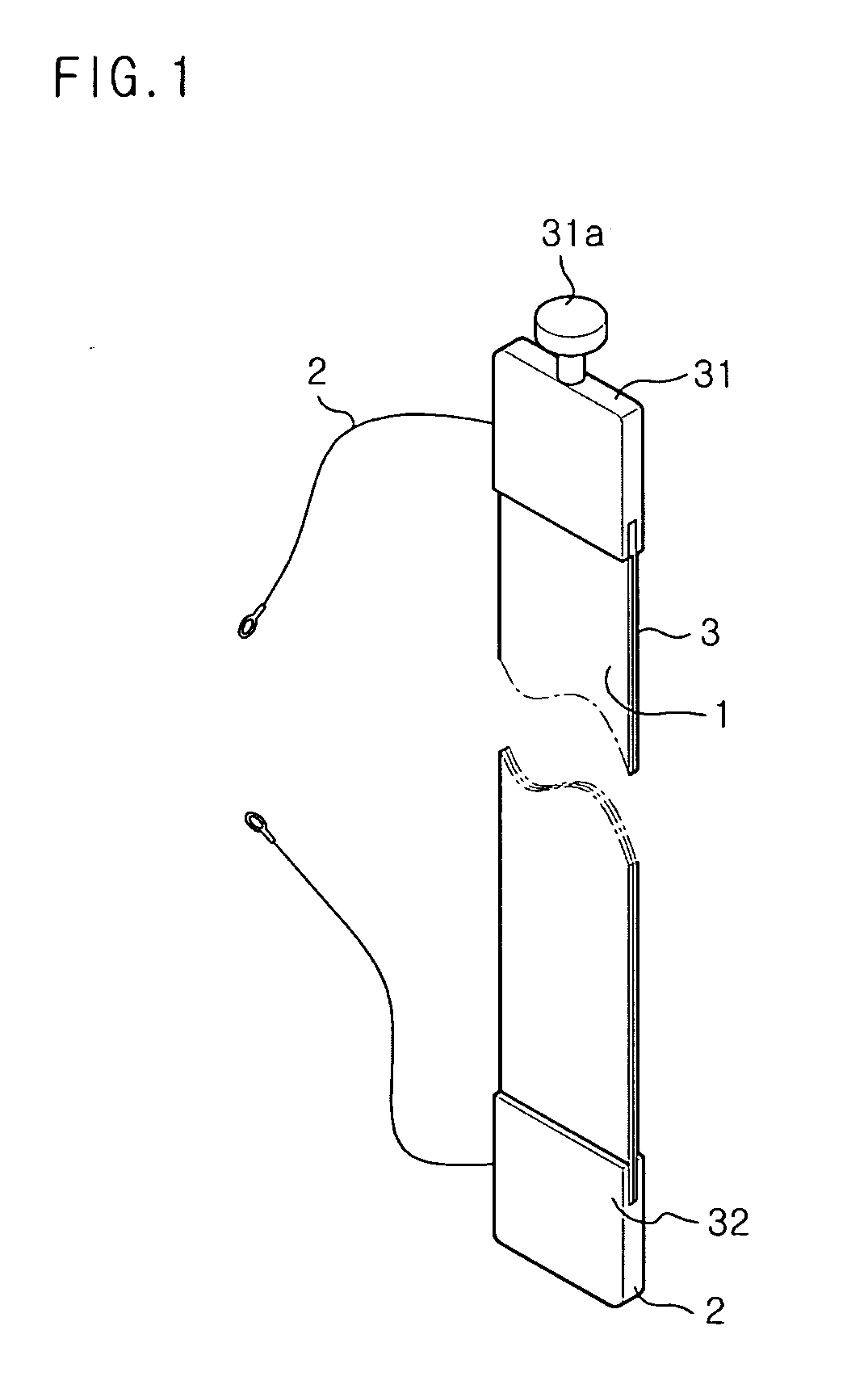
[0019]FIG. 1 is a perspective view illustrating a solar cell according to one embodiment of the present invention, and FIG. 2 is a perspective view illustrating a solar cell array of the solar cells shown in FIG. 1.

[0020] Referring to FIGS. 1 and 4, a blind type solar cell assembly according to the invention comprises a blind member 3 or 30, and a solar cell 1 or 10 installed on one side of the blind member 3 or 30.

[0021] The solar cell 1 or 10 has the same structure as a conventional solar cell, which comprises a semiconductor layer to generate electricity in response to light, and an electrode layer to transmit the electricity generated from the semiconductor layer, and thus detailed description thereof will be omitted hereinafter.

[0022] In this regard, the solar cell of the present invention is different from the conventional solar cell in that the sol...


PUM


Abstract

A blind type solar cell assembly has a blind structure to serve not only as a light shading plate but also as a light collecting device. The solar cell assembly comprises a plurality of solar cells, each being formed by stacking an electrode layer and a semiconductor layer, such that the solar cells are disposed on an outer surface of a blind member having an elongated plate shape, and electrically connected in parallel or in series with each other. A blind type solar cell array comprises a plurality of blind members connected with each other via two or more connection strings, solar cells respectively disposed on outer surfaces of the blind members so as to be electrically connected in parallel or in series with each other, and an electric wire to electrically connect the solar cells disposed on the blind members with each other in series or in parallel.

Description

BACKGROUND OF THE INVENTION [0001] 1. Field of the Invention [0002] The present invention relates to a solar cell, and more particularly, to a blind type solar cell, which has a shape of a blind so as to serve not only as a light shading plate but also as a light collecting unit. In addition, the present invention relates to a solar cell array, which comprises solar cells formed on outer surfaces of blind members such that the solar cells are connected with each other so as to act as blinds while collecting light at the same time. [0003] 2. Description of the Related Art [0004] Electric energy can be obtained with various electric power generators, one of which is a solar cell. [0005] The solar cell is a power generator which collects and converts solar energy into electric energy, and is generally used as a power source for a heater in a building or for small electric devices. [0006] The solar cell generally comprises a semiconductor device to convert solar energy into electric ene...

Claims


Application Information

Patent Timeline
IPC IPC(8): H02N6/00
CPCE06B9/36E06B9/386E06B2009/2476H01L31/0504Y02E10/50H02S20/00H02S30/20H01L31/042H02S20/30H02S40/36
Inventor LIM, SANG-HOON
Owner KOREA INST OF ENERGY RES
Why Eureka
Try Eureka