Mounting Structure For Storage Battery Device

a storage battery and mounting structure technology, applied in the direction of electric devices, cell components, tractors, etc., can solve the problems of possible breakage of the battery case and the batteries therein, and achieve the effect of preventing or reducing the damage to the storage battery devi

Inactive Publication Date: 2007-09-20
TOYOTA JIDOSHA KK
View PDF20 Cites 69 Cited by
  • Summary
  • Abstract
  • Description
  • Claims
  • Application Information

AI Technical Summary

Benefits of technology

[0006] It is an object of the invention to provide a mounting structure for a storage

Problems solved by technology

However, since the battery case is firmly mounted on the side members in the structure described in the aforementioned publication, the structure has the following problems.
If a side member is squeezed and deformed,

Method used


Image

  • Mounting Structure For Storage Battery Device
  • Mounting Structure For Storage Battery Device
  • Mounting Structure For Storage Battery Device

Examples


first embodiment

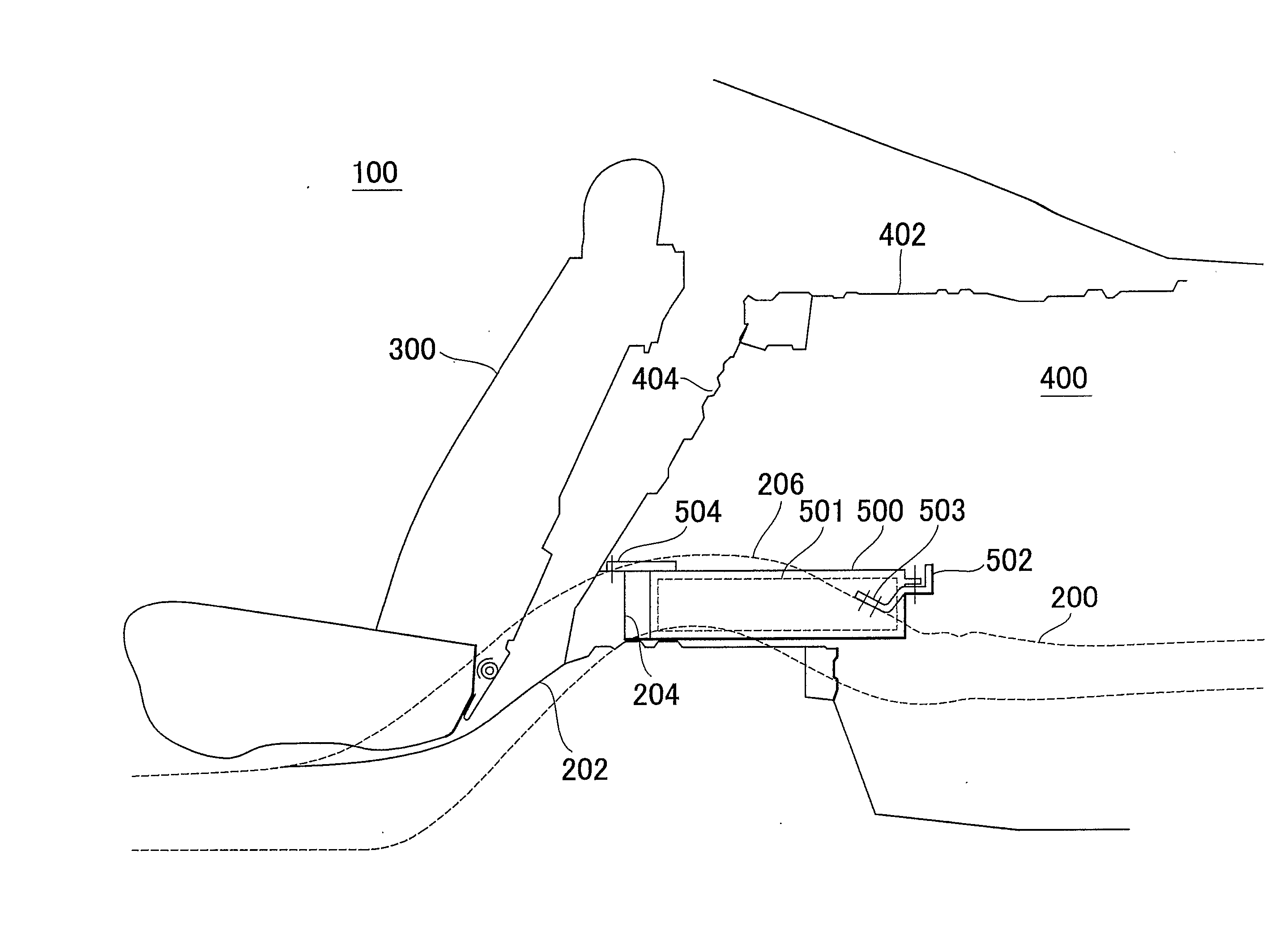
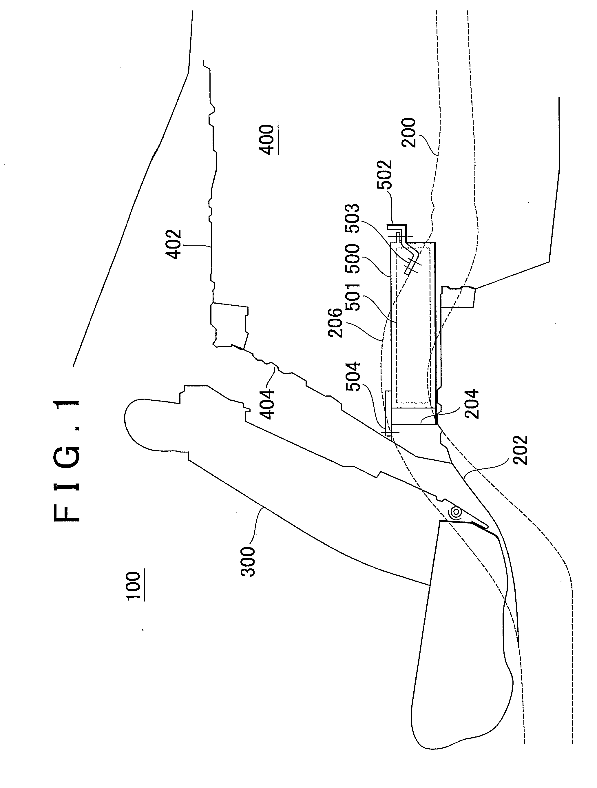
[0031] With reference to FIG. 1, a vehicle 100 to which a mounting structure for a storage battery device in accordance with a first embodiment of the invention is applied will be described. The vehicle 100 includes side members (side frames) 200, a floor panel 202, a cross member 204, a rear seat 300 provided in a passenger compartment, and a trunk compartment 400 provided rearward of the passenger compartment. The vehicle 100 is a sedan type vehicle in which the passenger compartment and the trunk compartment are partitioned.

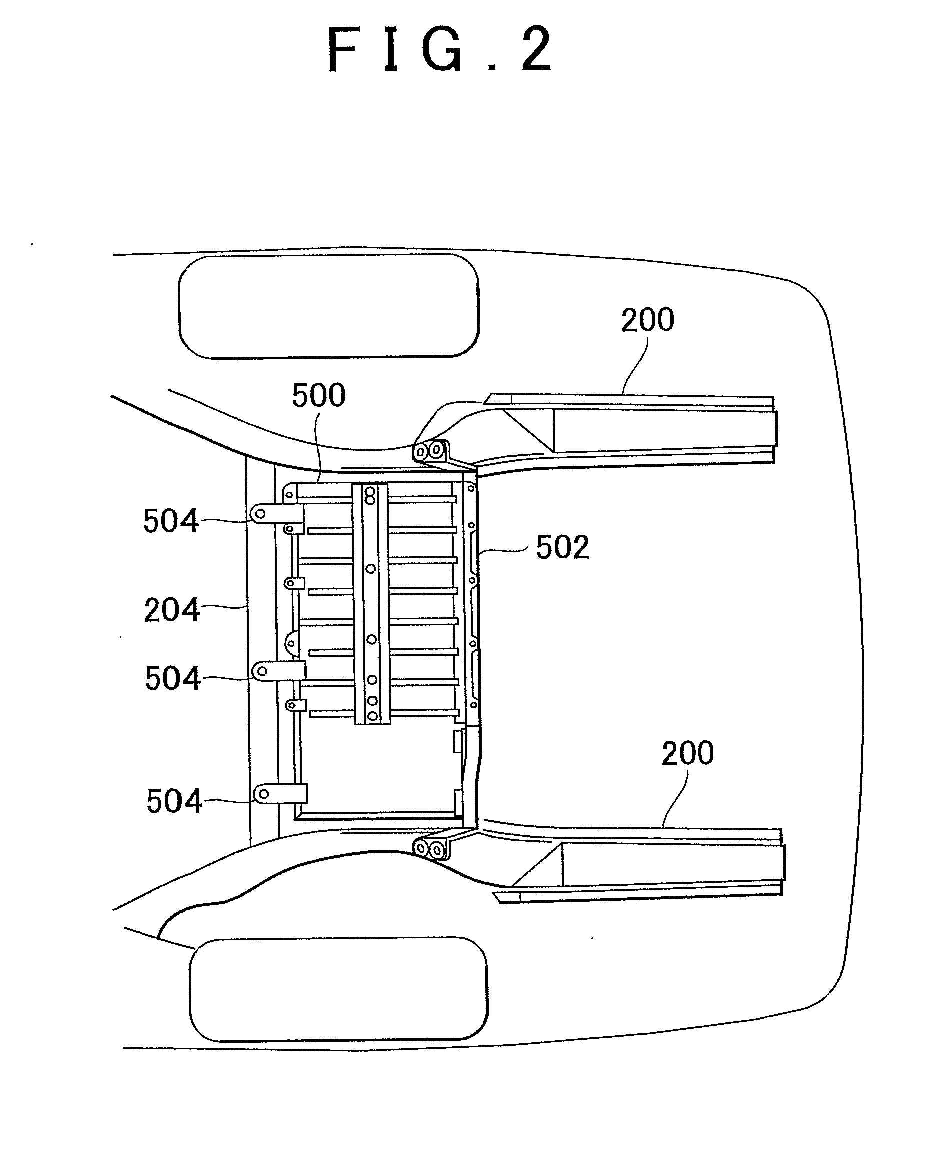
[0032] Each side member 200 includes an upwardly curved kick-up portion 206 at a location corresponding to a rear wheel (not shown). Two side members 200 are provided so that each side member 200 is positioned in a corresponding side portion of the vehicle 100. The floor panel 202 is provided between the two side members 200, and forms a floor surface of the vehicle 100. The cross member 204 is disposed at a location corresponding to forward portions of the k...

second embodiment

[0045] A vehicle to which a mounting structure for a storage battery device in accordance with a second embodiment of the invention is applied will be described with reference to FIGS. 5 and 6. Although in the first embodiment, the bridge is fixed to the side members via tie fixing portions positioned forward of the rearward end of the battery pack, a bridge in the second embodiment is fixed to the side members via rearward brackets that are positioned rearward of the rearward end of the battery pack. Other constructions of the second embodiment are the same as those of the first embodiment. The functions of those constructions are also the same as in the first embodiment. Therefore, detailed descriptions thereof will not be repeated.

[0046] As shown in FIG. 5, a bridge 506 is fixed to upper surfaces of the side members 200, via rearward brackets 508. The bridge 506 is disposed at a position that is rearward of the battery pack 500 and that is above the vertical position of a bottom...


PUM


Abstract

Two side members are provided so as to be in side portions of a vehicle. Each side member is provided with a kick-up portion curved upward. A cross member is provided so as to interconnect side surfaces of forward portions of the kick-up portions of the two side members. A forward portion of a battery pack is fixed to an upper surface of the cross member via forward brackets welded to the forward portion of the battery pack. A rearward portion of the battery pack is fixed to upper surfaces of rearward portions of the kick-up portions of the two side members via a bridge provided so as to interconnect the two side members.

Description

FIELD OF THE INVENTION [0001] The invention relates to a mounting structure for a storage battery device and, more particularly, to a mounting structure for a storage battery device installed in a vehicle. BACKGROUND OF THE INVENTION [0002] Recently, attention has been drawn to vehicles run by drive power from an electric motor, for example, hybrid vehicles, fuel cell vehicles, electric vehicles, etc., as environmental protection measures. Such a vehicle is equipped with a battery, a capacitor, or the like for storing electric power to be supplied to an electric motor. [0003] Japanese Patent Application Publication No. JP-A-7-117489 discloses a battery mounting structure for an electric vehicle which allows a reduction of the space in a cabin which is taken up by the battery. The battery mounting structure for an electric vehicle described in Japanese Patent Application Publication No. JP-A-7-117489 is a structure for mounting a battery in an electric vehicle that has side members (...

Claims


Application Information

Patent Timeline
IPC IPC(8): B60R16/04B60K1/04H01M2/10B62D25/20
CPCB60K1/04B60L3/0007B60L11/1877B60L2200/26Y02T10/7005Y02T10/705B62D21/152B60L50/66Y02T10/70
Inventor WATANABE, KONAGASE, SYUJI
Owner TOYOTA JIDOSHA KK
Why Eureka
Try Eureka