Exhaust gas purification device of internal combustion engine

a technology of exhaust gas purification and internal combustion engine, which is applied in the direction of machines/engines, functional valve types, transportation and packaging, etc., can solve the problems of reducing the size of the exhaust gas purification device, and achieve the effects of preventing or reducing the damage of the solution supply line caused by freezing of the exhaust gas purification solution remaining in the solution supply line, preventing corroding, and effective vacuating the solution supply lin

Inactive Publication Date: 2011-02-15
AISAN IND CO LTD
View PDF8 Cites 20 Cited by
  • Summary
  • Abstract
  • Description
  • Claims
  • Application Information

AI Technical Summary

Benefits of technology

[0007]According to the exhaust gas purification device, when the internal combustion engine is operated, the exhaust gas purification solution in the storage tank is selected by the gas-liquid selection device. As a result, the solution is aspirated into the solution supply line by the supply pump and is then injected into the exhaust passage, so that the exhaust gas can be purified. Conversely, when the internal combustion engine is stopped, the air in the storage tank is selected by the gas-liquid selection device. As a result, the air is aspirated by the supply pump and is then pumped through the solution supply line, so that the exhaust gas purification solution in the solution supply line can be discharged therefrom. Thus, the solution supply line can be vacuated. Therefore, damage of the solution supply line caused by freezing of the exhaust gas purification solution in the solution supply line can be effectively pre rented or reduced.
[0008]Further, the exhaust gas purification device does not require a pressure gas container, a pressure pump or other such devices. This may lead to reduced size of the exhaust gas purification device.
[0010]According to the exhaust gas purification device, when the internal combustion engine is operated, the flow path switching device is switched to the normal flow mode. As a result, the exhaust gas purification solution in the storage tank is aspirated into the solution supply line by the supply pump and is then injected into the exhaust passage, so that the exhaust gas can be purified. Conversely, when the internal combustion engine is stopped, the flow path switching device is switched to the reverse flow mode. As a result, the exhaust gas purification solution remaining in the solution supply line can be returned to the storage tank. Thus, the solution supply line can be vacuated. Therefore, damage of the solution supply line caused by freezing of the exhaust gas purification solution remaining in the solution supply line can be effectively prevented or reduced.
[0011]Further, as described above, when the internal combustion engine is stopped, the exhaust gas purification solution remaining in the solution supply line can be reliably returned to the storage tank. Therefore, the exhaust pipe can be prevented from corroding. Further, an unfavorable odor is prevented from being emitted via the exhaust pipe. In addition, waste of the exhaust gas purification solution can be reduced or prevented.

Problems solved by technology

This may lead to reduced size of the exhaust gas purification device.

Method used


Image

  • Exhaust gas purification device of internal combustion engine
  • Exhaust gas purification device of internal combustion engine
  • Exhaust gas purification device of internal combustion engine

Examples


first embodiment

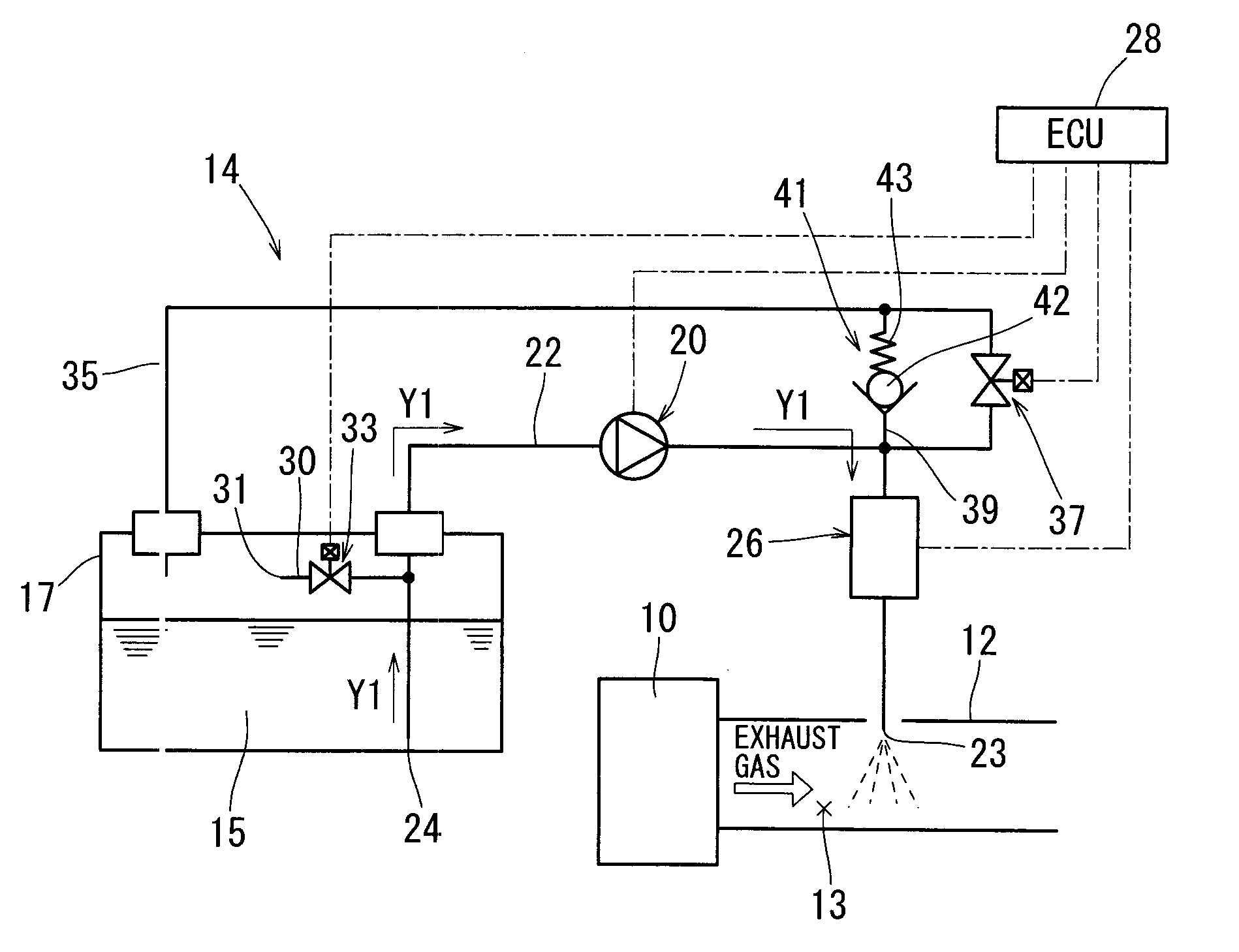
[0026]A first embodiment of the present invention will be described with reference to FIGS. 1 to 7. This embodiment of the present invention is directed to an exhaust gas purification device in which an aqueous solution of urea is used as an exhaust gas purification solution, i.e., a liquid reducing agent, so that nitrogen oxides (NOx) contained in an exhaust gas of an internal combustion engine is purified via a catalytic reductive reaction.

[0027]As shown in FIG. 1, an exhaust gas discharged from an internal combustion engine 10, e.g., a diesel engine or other such engines, may preferably be discharged into the atmosphere through an exhaust gas purification catalyst or NOx reduction catalyst (not shown) that is received in an exhaust pipe 12, i.e., in an exhaust passage 13.

[0028]An exhaust gas purification device 14 attached to the internal combustion engine 10 has a storage tank 17 that can store an exhaust gas purification solution 15. The exhaust gas purification solution 15 is ...

first modified form of first embodiment

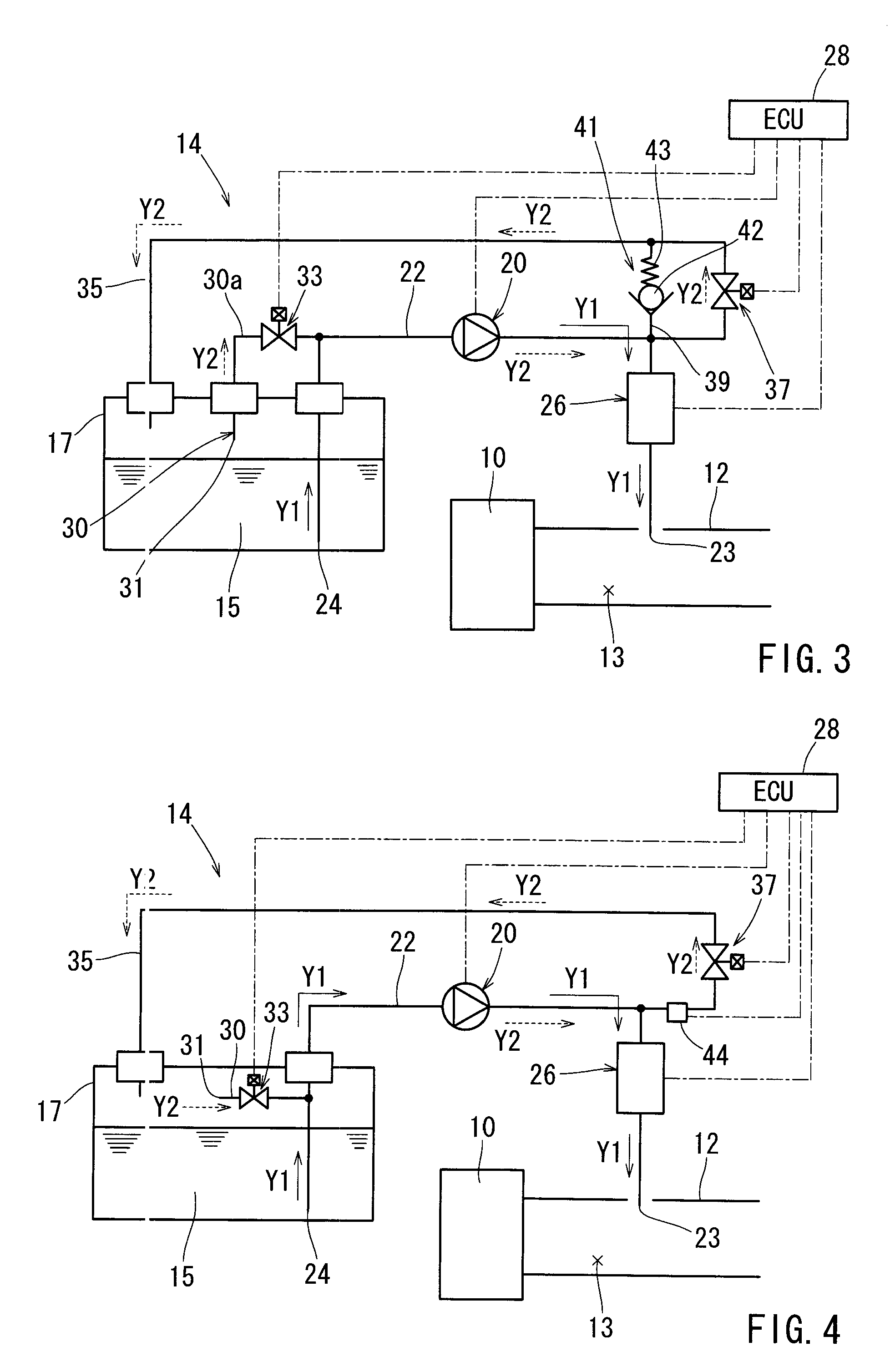
[0046]As shown in FIG. 3, in a first modified form of the first embodiment, one end of the air aspiration line 30 is connected to the solution supply line 22 via an extension line 30a outside the storage tank 17. Further, the first on-off valve 33 is disposed on the extension line 30a. According to this modified form, the first on-off valve 33 is positioned outside the storage tank 17. This may lead to easy attachment and maintenance of the first on-off valve 33. In addition, the on-off valve 33 and associated parts (electric wires) can be effectively prevented or inhibited from corroding.

second modified form of first embodiment

[0047]As shown in FIG. 4, in a second modified form of the first embodiment, the bypass line 39 and the relief valve 41 are omitted. Instead, the return line 35 is provided with a pressure sensor 44 that is capable of detecting a pressure therein. The pressure sensor 44 is positioned above the second on-off valve 37 and is electrically connected to the ECU 28. The ECU 28 can control a discharge pressure of the supply pump 20 based on a signal output from the pressure sensor 44. Alternatively, the ECU 28 can control the second on-off valve 37 based on the signal output from the pressure sensor 44, so as to stabilize a pressure applied to the flow rate control valve 26. As will be appreciated, the pressure sensor 44 is not limited to a special sensor provided that the pressure sensor 44 can detect the pressure in the portion of the solution supply line 22 positioned between the supply pump 20 and the flow rate control valve 26 (including the portion of the return line 35 positioned ab...


PUM


Abstract

An exhaust gas purification device of an internal combustion engine is taught that preferably include a storage tank storing an exhaust gas purification solution that is injected into an exhaust passage of the internal combustion engine, a solution supply line that is constructed to introduce the exhaust gas purification solution from the storage tank to the exhaust passage, a supply pump disposed on the solution supply line, and a gas-liquid selection device. The gas-liquid selection device is constructed to selectively introduce the exhaust gas purification solution and air into the solution supply line.

Description

[0001]This application claims priority to Japanese patent application serial number 2006-342492, the contents of which are incorporated herein by reference.BACKGROUND OF THE INVENTION[0002]The present invention relates to an exhaust gas purification device of an internal combustion engine that is used in a vehicle such as an automobile. Particularly, the present invention relates to an exhaust gas purification device of an internal combustion engine, which may purify nitrogen oxides (NOx) contained in an exhaust gas of the internal combustion engine using an exhaust gas purification solution.[0003]An exhaust gas purification device of an internal combustion engine, e.g., a diesel engine or a gasoline engine, is taught by, for example, Japanese Laid-Open Patent Publication No. 9-511807. In this device, an aqueous solution of urea contained in a storage tank is injected into an exhaust gas of the internal combustion engine via a solution supply line, so that the exhaust gas is purifie...

Claims


Application Information

Patent Timeline
Patent Type & Authority Patents(United States)
IPC IPC(8): F01N3/00
CPCF01N3/2066F01N2610/02F01N2610/1406F01N2610/1473F01N2610/1493Y02T10/24Y10T137/86831Y10T137/86002Y02T10/12
Inventor NISHIBU, HIDEAKIAOKI, TSUNEAKI
Owner AISAN IND CO LTD
Why Eureka
Try Eureka