Automation fallback to P2P LSPs for mLDP built multipoint-trees

a multipoint tree and automatic fallback technology, applied in data switching networks, special service provisioning for substations, digital transmission, etc., can solve the problems of prohibitively expensive creation of private networks, and problems can arise in mpls networks containing lsrs which are not mldp enabled

Active Publication Date: 2007-09-20
CISCO TECH INC
View PDF33 Cites 17 Cited by
  • Summary
  • Abstract
  • Description
  • Claims
  • Application Information

AI Technical Summary

Problems solved by technology

Since it can be prohibitively expensive to create a private network that spans great distances, many businesses opt to rely upon a third-party provider's network to provide connectivity between network elements at disparate geographic sites.
However, problems can arise in MPLS networks which contain LSRs which are not mLDP enabled.

Method used


Image

  • Automation fallback to P2P LSPs for mLDP built multipoint-trees
  • Automation fallback to P2P LSPs for mLDP built multipoint-trees
  • Automation fallback to P2P LSPs for mLDP built multipoint-trees

Examples


Embodiment Construction

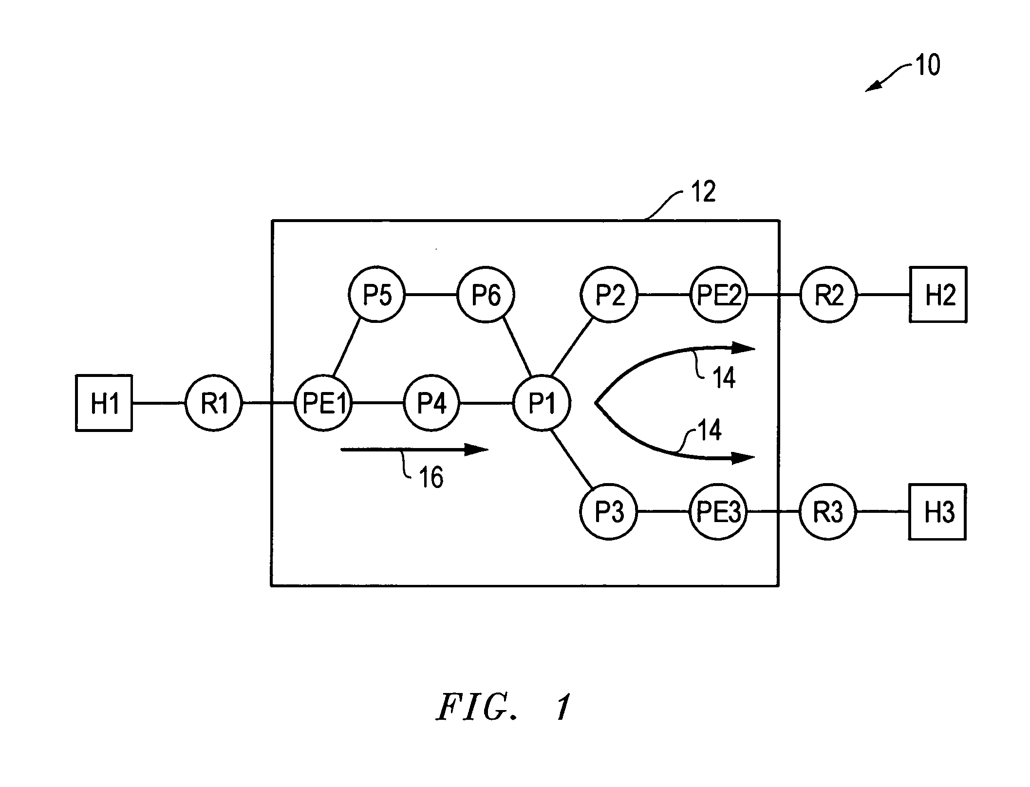
[0017] U.S. patent application Ser. No. 11 / 267,674 describes a method for creating a P2MP LSP within an MPLS enabled network. Each of the LSRs within the MPLS network described in U.S. patent application Ser. No. 11 / 267,674, are presumed to be mLDP enabled. To illustrate, FIG. 1 is an exemplary network 10 consisting of hosts H1-H3 coupled to PIM enabled routers R1-R3, respectively. FIG. 1 also shows router R1 coupled to routers R2 and R3 via an MPLS network 12. MPLS network 12 includes MPLS enabled edge LRSs PE1-PE3 coupled to MPLS enabled core LSRs P1-P6. In addition to being MPLS enabled, edge LSRs PE1-PE3 are PIM enabled and coupled to routers R1-R3, respectively. For purposes of explanation, it will be temporarily presumed that each of the LSRs within MPLS network 12 is mLDP enabled or capable of operating in accordance with the invention described in U.S. patent application Ser. No. 11 / 267,674.

[0018] Presume host HI is a source that generates multicast data packets destined fo...


PUM


Abstract

A method of using a point-to-point (P2P) label switched path (LSP) to transmit multicast data packets partially through a multiprotocol label switched (MPLS) network when one or more label switched routers (LSRs) of the MPLS are not multicast label distribution protocol (mLDP) enabled. The P2P LSP can be used to transmit multicast data packets to the head end of a point-to-multipoint (P2MP) LSP created with mLDP enabled LSRs. The P2MP LSP can be used to transmit the multicast data packets through the MPLS network to intended receivers that are external to the MPLS network. When configuring the P2MP LSP, an mLDP enabled LSR receives a first message from a non-mLDP enabled MPLS core router in response to sending a label mapping message to the non-mLDP enabled MPLS core router. In response, a directed LDP session is created between the mLDP enabled LSR and an edge LSR in one embodiment in response to receiving the first message from an MPLS enabled core router. The directed LDP session can be used to transmit a label mapping message to an ingress LSR.

Description

CROSS-REFERENCE TO RELATED APPLICATIONS [0001] The present patent application claims priority to U.S. patent application Ser. No. 11 / 267,674 filed Nov. 4, 2005, Attorney Docket No. CIS0261US, entitled “In-Band Multicast Signaling Using LDP.” This application is incorporated by reference herein in its entirety.BACKGROUND OF THE INVENTION [0002] Businesses employ networks to interconnect their computers, servers, storage devices, and other network elements. As a business grows, so can its network, increasing the number of network elements coupled to the network, the number of network links, and also geographic diversity. A business' network elements can be scattered throughout a city, a state, a country, or the world. Since it can be prohibitively expensive to create a private network that spans great distances, many businesses opt to rely upon a third-party provider's network to provide connectivity between network elements at disparate geographic sites. In order for the business' ne...

Claims


Application Information

Patent Timeline
Patent Type & Authority Applications(United States)
IPC IPC(8): H04L12/28H04L45/50
CPCH04L45/00H04L45/04H04L45/50H04L45/502H04L45/46H04L2012/5642H04L2012/5641H04L12/1845H04L12/18H04L2012/6416
Inventor WIJNANDS, IJSBRANDBOERS, ARJENMEYLOR, JOHN S.
Owner CISCO TECH INC
Why Eureka
Try Eureka