Screw

a screw and screw body technology, applied in the field of screws, can solve the problems of affecting the stability of the screw, the screw cannot be completely and the user always has to gradually exercise more power, so as to prevent the screw from loosening off the article, the screw can be easily and quickly moved into the article, and the screw can be buried in the article more stably.

Inactive Publication Date: 2007-09-20
CHANNG CHIN IND CORP
View PDF16 Cites 64 Cited by
  • Summary
  • Abstract
  • Description
  • Claims
  • Application Information

AI Technical Summary

Benefits of technology

[0006] The main characteristics of the invention are a head and a shank extending down from the head. The shank formed round or triangular is provided with a first clockwise-threaded portion located from an intermediate portion to a lower end, a counterclockwise-threaded portion located from the upper end of the first clockwise-threaded portion to the head, and a second clockwise-threaded portion on a lower end section of the first clockwise-treaded portion and having one-third length of the first clockwise-threaded portion and threads between two threads of the first clockwise-threaded portion. Therefore, the lower end section of the shank has double threads of a smaller pitch, able to permit the screw move into articles more easily and rapidly. Moreover, the counterbalancing function of the clockwise and the counterclockwise threads can keep the screw buried in the articles more stably, preventing the screw from loosening off articles by non-manual factor.

Problems solved by technology

But, while a conventional screw is screwed into articles deeper and deeper, it is to encounter a counter force caused by the articles, because the articles are only squeezed not cut.
So a user always has to gradually exercise more power, taking a long time to keep screw a conventional screw into articles completely.

Method used


Image

  • Screw
  • Screw
  • Screw

Examples


Embodiment Construction

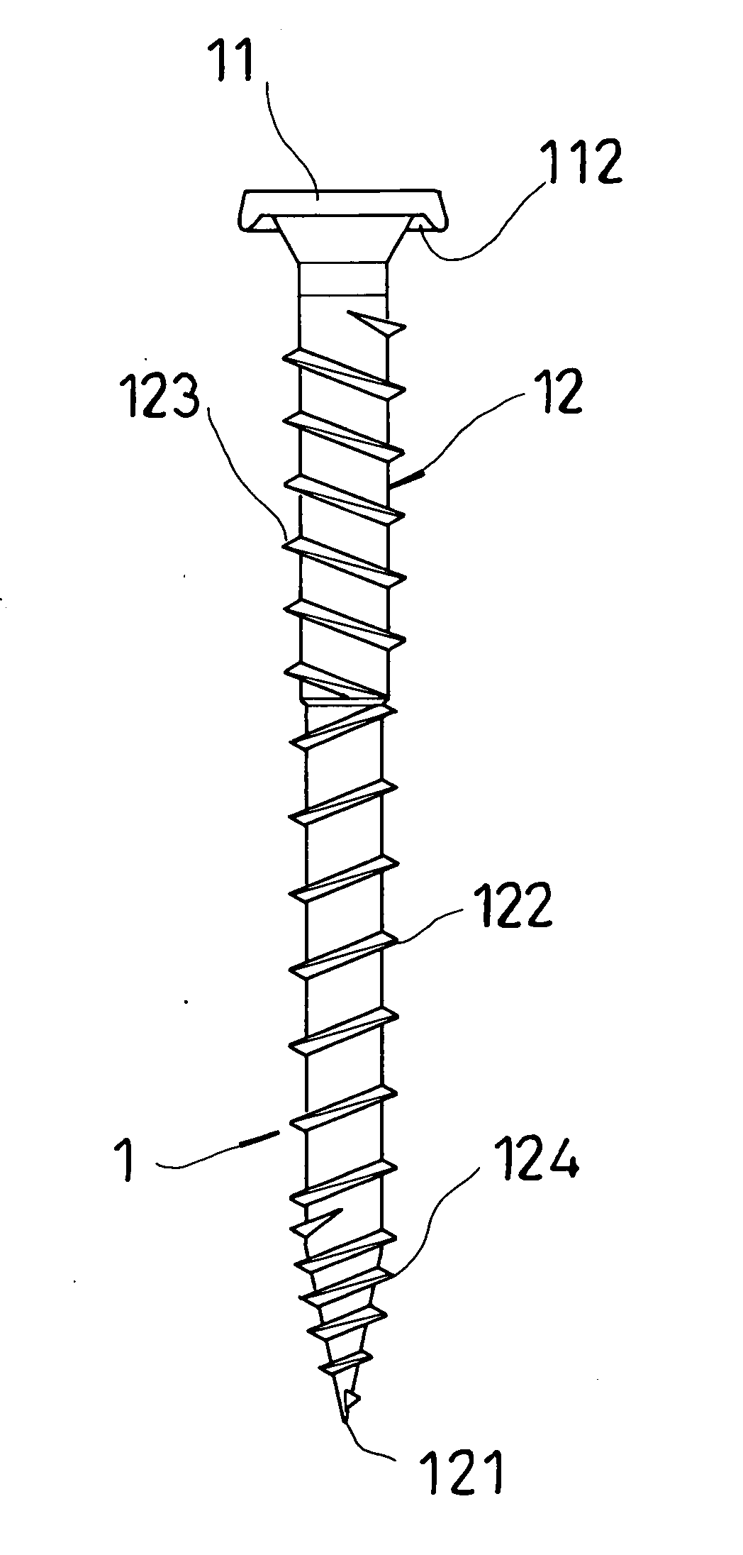
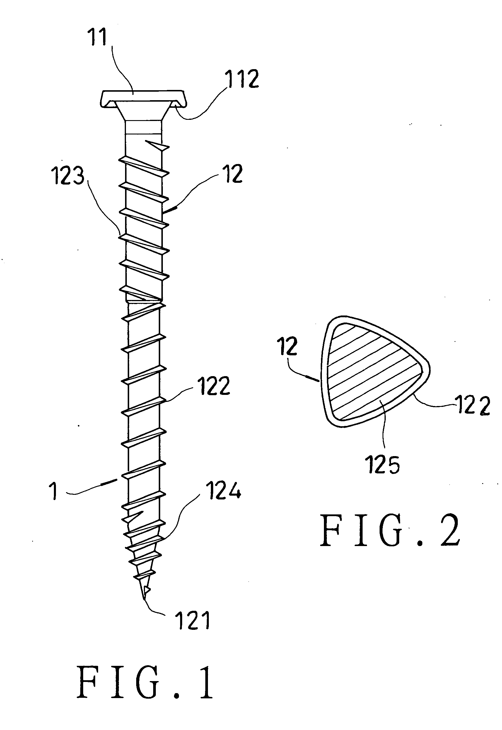
[0012] As shown in FIG. 1, a first preferred embodiment of a screw 1 in the present invention includes a head 11 and a shank 12 extending down from the head 11.

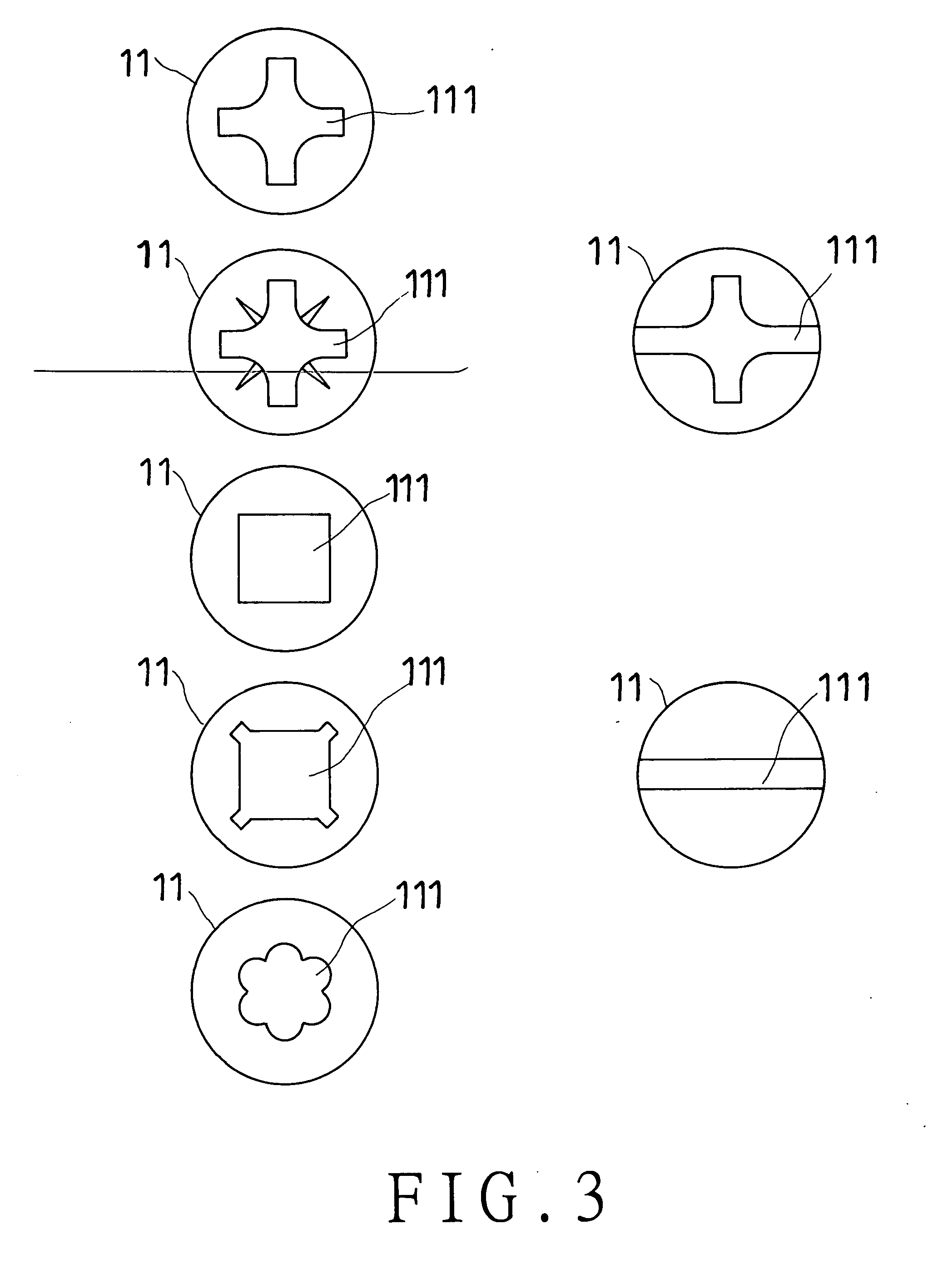
[0013] The head 11 is provided with a recess 111 in the top surface for a tool such as a screwdriver to fit closely in, as shown in FIGS. 3 and 4, and an annular groove 112 formed around the circumference of the bottom to shape the head 11 as a reverse U in a cross-sectional view.

[0014] The shank 12 is provided with a conical sharp point 121 at the bottom end, a first clockwise-threaded portion 122 located from a preset point in an intermediate portion to the bottom end, a counterclockwise-threaded portion 123 located from the head 11 to an upper end of the first clockwise-threaded portion 122, and a second clockwise-threaded portion 124 located in a lower end section of the first clockwise-threaded portion 122 and having one-third length of the first clockwise-threaded portion 122 and threads between two threads of the fir...


PUM

PropertyMeasurementUnit
lengthaaaaaaaaaa
diameteraaaaaaaaaa
circumferenceaaaaaaaaaa

Abstract

A screw includes a head and a shank extending down from the head. The shank is provided with a first clockwise-threaded portion from an intermediate portion to the bottom end, a counterclockwise-threaded portion the upper end of the first clockwise-threaded portion to the head, and a second clockwise-threaded portion formed in a lower end section of the first clockwise-threaded portion and having one-third length of the clockwise-threaded portion and threads between two threads of the first clockwise-threaded portion. Therefore, the lower end section of the shank has a smaller pitch able to permit the screw move into articles more easily and rapidly. Moreover, the counterbalancing function of the clockwise and the counterclockwise threads can keep the screw buried in the articles more stably without loosening easily.

Description

BACKGROUND OF THE INVENTION [0001] 1. Field of the Invention [0002] This invention relates to a screw, particularly to one able to save power and to be screwed with articles stable and not easily loosen off. [0003] 2. Description of the Prior Art [0004] Usually, a screw is used to keep non-metallic articles that are made of plastics or wood etc. fastened together via screwing it directly into them. Because a screw has a higher harness than the articles to be screwed, it can be screwed into the articles to squeeze and form threaded grooves inside them, so as to keep the articles tightly fastened together by the screw. But, while a conventional screw is screwed into articles deeper and deeper, it is to encounter a counter force caused by the articles, because the articles are only squeezed not cut. So the deeper the screw is forced in, the more the contacting area between the screw and the articles is increased. So a user always has to gradually exercise more power, taking a long time...

Claims


Application Information

Patent Timeline
Patent Type & Authority Applications(United States)
IPC IPC(8): F16B35/04
CPCF16B23/0015F16B23/0023F16B23/003F16B23/0038F16B25/0015F16B2033/025F16B25/0068F16B25/0078F16B25/10F16B35/041F16B35/06F16B25/0057
Inventor LIN, CHING-KUEI
Owner CHANNG CHIN IND CORP
Why Eureka
Try Eureka